5 Conversion and maintenance
122 Festo – P.BE-MPA-EN – 1309f – English
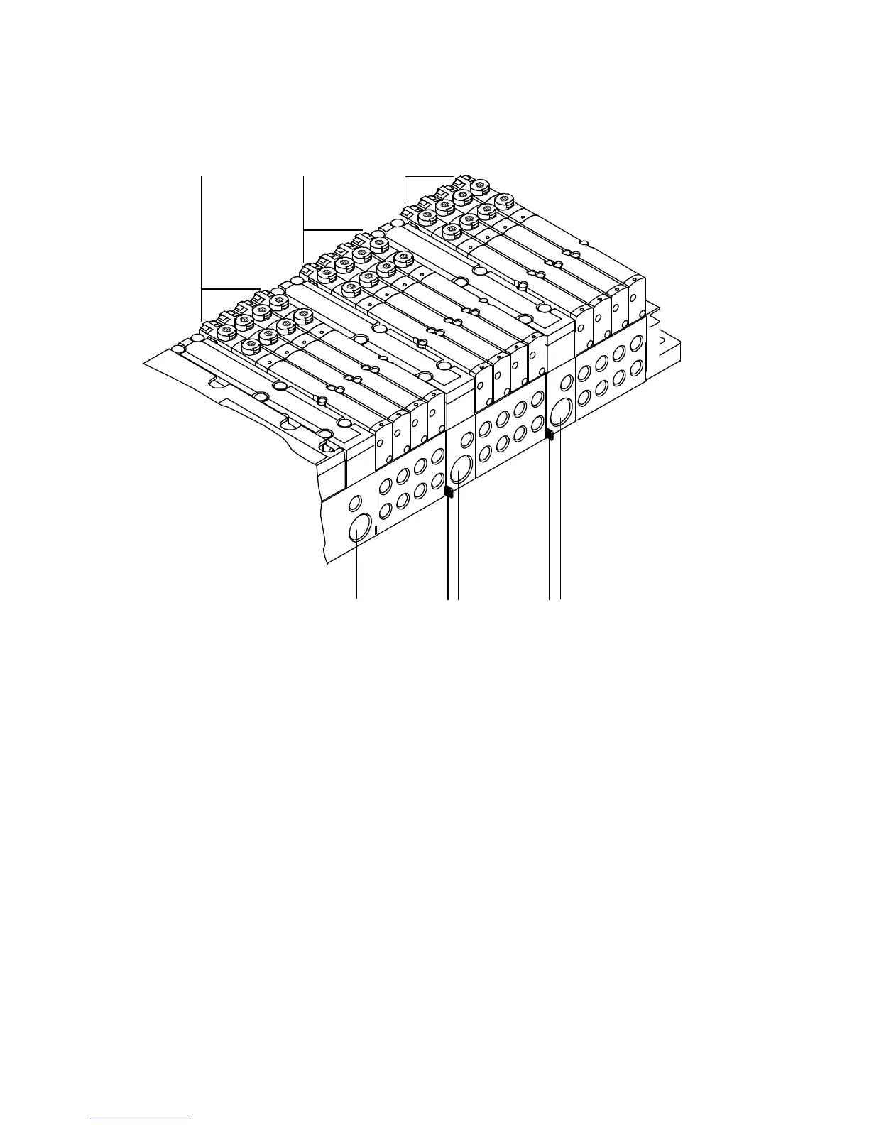
The fo llowing diagram shows the structure of pressure zones using as an example an MPA-S valve ter-
minal with CPX terminal.
12 3
45567
1 Valve sub-bases of the 1st pressure zone
2 Valve sub-bases of the 2nd pressure zone
3 Valve sub-bases of the 3rd pressure zone
4 Air supply plate with port (1) for compressed
air supply to the 3rd pre ssure zone
5 Marking of the separating seal with pressure
zone separation
6 Air supply plate with port (1) for compressed
air supply to the 2nd pressure zone
7 Pneumatic interface with connection (1) for
compressed air supply to the 1st pressure
zone
Fig. 5.17 Example: MPA-S valve terminal with CPX ter minal and 3 pressure zones
5.4.3 Adding valve positions
You can easily adapt the MPA-S valve terminal to the requirements of your machine or system by adding
valve positions. The smallest extension unit is a sub-base with 4 valve positions ( MPA1) or 2 valve posi-
tions (MPA2).