3 Mounting and installation
Festo – P.BE-MPA-E N – 1309f – English 49
3.2 Mounting variants
You can mount the MPA-S valve terminal in one of two ways:
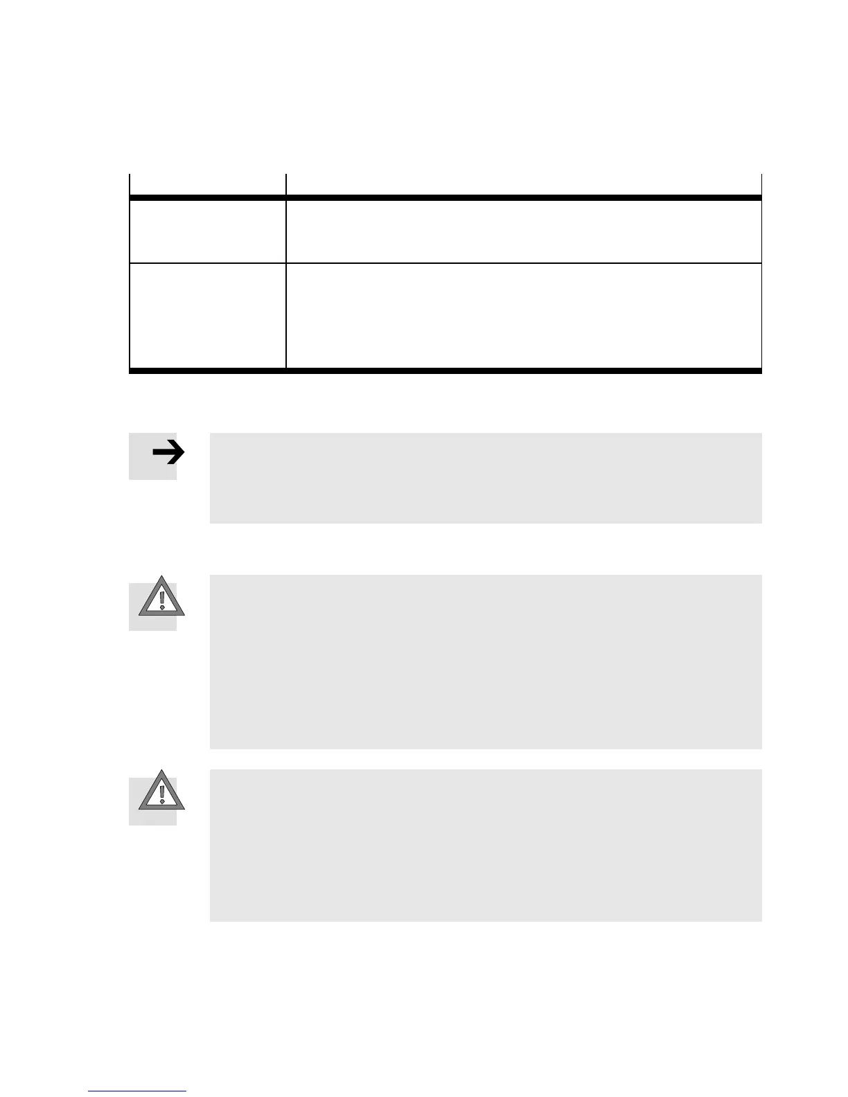
Mounting method
Description
H-rail The MPA-S valve terminal is suitable for mo unting onto an H-rail (DIN
mounting rail as per EN 60715). There is a guide groove on the back cover
for hanging the valve terminal onto the H-rail.
Wall The multi-pin plug connection plate or the pneumatic interface and the end
plates contain holes for wall mounting. For MPA-S valve terminals that are
longer than 280 mm, additional mounting brackets on the air supply plate
are required ( instructions on vibration and shock in Appendix A,
Tab. A . 4).
Tab. 3.1 Mounting methods of the MPA-S valve terminal
Note
• Mount the MPA-S valve terminal so that there is sufficient space for heat dissipation
and ensure that the maximum limits for temperatures are observed ( Technical
data).
3.2.1 Mounting/dismounting on H-rails
Caution
H-rails with mounted valve terminals can break if they are subjec ted to vibration e x-
ceeding severity level 1:
– 0.15mmpathat15…58Hz
– 2 g acceleration at 58...150 Hz
This can damage the valve terminal, your machine or your system.
• In this case use wall mounting.
• Note the permitted values for vibration and shock in appendix A “Technical data”.
Caution
Mounting on H-rails without an H-rail clamping unit is impermissible.
• If the terminal is mounted in a sloping po sitio n or if it is subjected to vibration loads,
secure the H-rail clamping unit additionally
– against sliding down with the retainin g screw intended for this purpose
( Tab. 3.2 and Fig. 3.1)
– against unintentional loosening/opening.