3 Mounting and installation
50 Festo – P.BE-MPA-EN – 1309f – English
To mount on H-rails, you need the mounting kit CPX-CPA-BG-NRH. This mounting kit con-
sists of 3 clamping components and 3 screws M4x12.
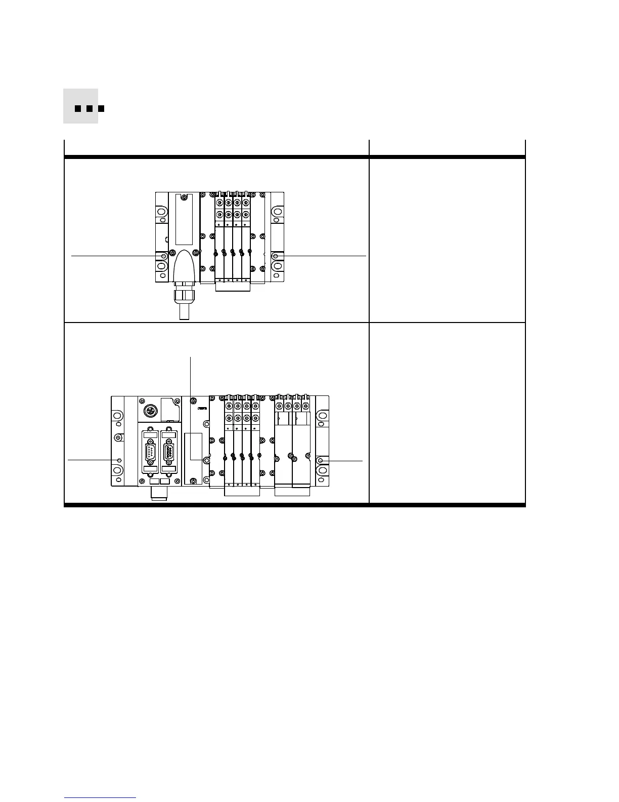
Variant
Mounting points
MPA-S valve terminal with multi-pin plug connection Required mounting of the H-rail
clamping units:
– In the right end plate and the
multi-pin plug connection
plate:
each one M4-screw 1
1
1
MPA-S valve terminal with CPX terminal Required mounting of the H-rail
clamping units:
–intheendplates:
each one M4 screw 1
– in the pneumatic interface:
one M4 screw 2
1
2
1
Tab. 3.2 Required mounting points for mounting on H-rails
Mounting
Proceed as follows:
1. Make sure the mounting surface can support the MPA -S valve terminal (weights A ppendix A.1,
Tab. A . 1 ) .
2. Mount the H-rail ( DIN mounting rail E N 60715 - 35x7.5; width 35 mm, height 7.5 mm). Make sure
ther e is sufficient space for connecting the power supply cables and tubing. Fasten the H-rail to the
mounting surf ace at intervals of approx. every 100 mm.
3. Mount the H-rail clamping units at all required mounting points ( Tab. 3.2). Make sure that the
clamping component is horizontal to the H-rail.
4. Hang the MP A-S v alve terminal onto the H-rail ( Fig. 3.1, arrow A).
5. Swing the MPA-S valve terminal onto the H-rail ( Fig. 3.1, arrow B).