3 Mounting and installation
Festo – P.BE-MPA-E N – 1309f – English 51
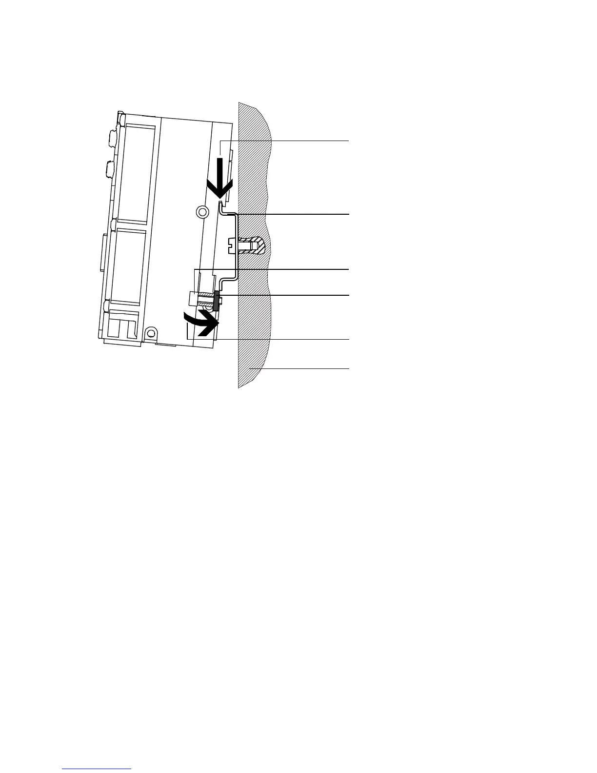
(A)
(B)
1
2
4
3
1 H-rail
2 Retaining screw of the H-rail clamping unit
3 Clamping component of the H-rail clamping
unit
4 Mounting surface
Fig. 3.1 Mounting of the M PA-S valve terminal on an H-rail
6. Turn the clamping components for mechanical interlock vertically behind the H-rail ( Fig. 3.2,
arrow A). Then tighten the retaining screws of the H-rail clamping unit with 1.3 Nm to secure the
MPA-S valve terminal against tilting or sliding.