5 Conversion and maintenance
Festo – P.BE-MPA-E N – 1309f – English 127
5.4.5 Adding a pressure sensor plate
For expansion you will need:
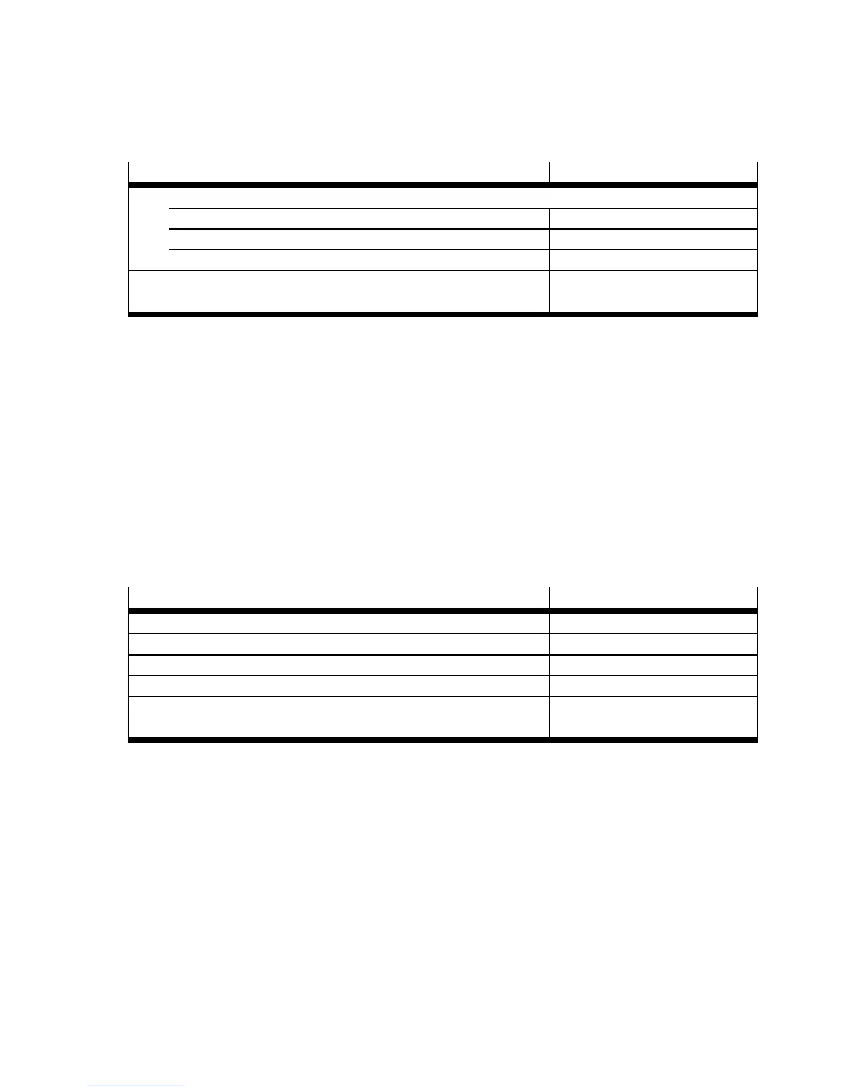
Components
Type
One of the subseque nt pressure sensor plates:
– For displaying the opera ting pressure in channel (1) VMPA-FB-PS -1
– For displaying the pressure in exh aust ducts (3) and (5) VMPA-FB-PS-3/5
– For displaying an external pressure (P1) VMPA-FB-PS-P1
Also, a seal without channel separation or a separating seal with
channel separation
chapter 2, Tab. 2.9
Tab. 5.12 Pressure sensor plates
Mounting
Proceed as follows:
1. Loosen the electric and pneumatic c onnections and then remove the M PA-S valve terminal from its
mounting surface ( chapter 3).
2. Mount t he pressure sensor plate as described in the mounting instructions VMPA-FB-PS-...-... .
3. Mount the MPA-S valve terminal onto the mounting surface ( chapter 3, “Wall mounting” or
“H-rail mounting”).
4. Then install the pneumatic and electrical connections ( chapter 3).
5.4.6 Adding a propor tional pressure regulator
For expansion you will need:
Components
Type
Proport io nal pressure regulator VPPM-…TA-L-1-F-0L…
Electronics module VMPA-FB-E MG-P1
Sub-base VMPA-FB-AP-P1
Interlinking board MPA
Also, a seal without channel separation or a separating seal with
channel separation
Tab. 2.9
Tab. 5.13
Components of the propor tional pressure regulator
Dismantling
Proceed as follows:
1. Loosen the electric and pneumatic c onnections and then remove the M PA-S valve terminal from its
mounting surface ( chapter 3).
2. Dismantle the sub-base or air supply plate at the point where you wish to extend the terminal
( section 5.3.7).