3 Mounting and installation
Festo – P.BE-MPA-E N – 1309f – English 55
Dismounting
Proceed as follows:
1. Secure a hanging-mounted MPA-S v alve terminal from falling down before you loosen it from the
mounting surface.
2. Loosen the mounting screws ( Tab. 3.3).
3. Remove the MPA-S valve terminal from the mounting surface.
3.2.4 Additional fastening of the valve terminal
The use of additional attachments is required under the following conditions ( Tab. 3.4):
– for MPA-S valve terminals that exc eed a length of 280 mm
– for increased vibration/shock loads (limits for vibrations and shock see Appendix A, Tab. A.4)
– for MPA-S valve terminals equipped with t hree or more CPX interlinking blocks made of plastic
– for MPA-S valve terminals equipped with four or mor e CPX interlinking blocks made of metal.
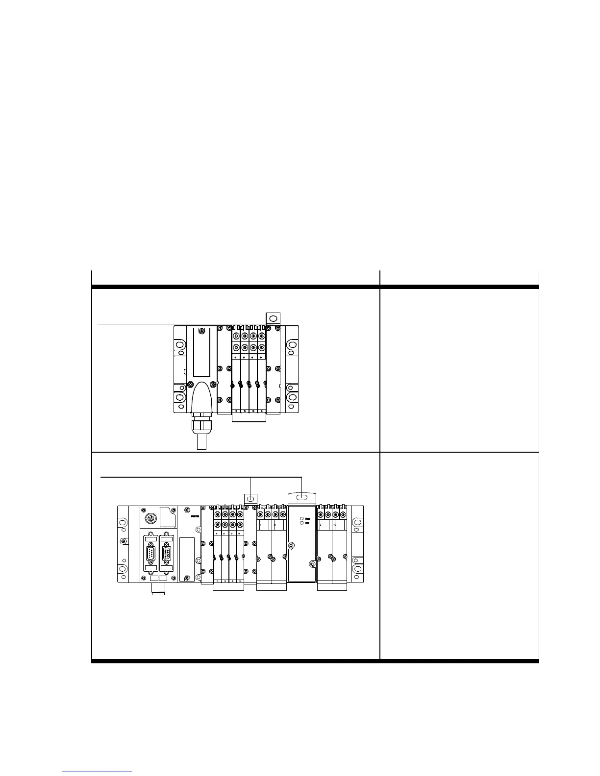
Variant
Mounting points
MPA-S valve terminal with multi-pin plug connection Additional mounting points:
– For each mounting bracket on
the pneumatic air supply plate
( also
i
nstructions in
Appendix A, Tab. A.4): one M6
screw 1
1
MPA-S valve terminal with CPX terminal
1
Additional mounting points:
– For each mounting bracket on
the pneumatic supply plate o r
proport ional pressure
regulator ( also instructio ns
in a ppendix A, Tab. A.4):
one M6 screw 1
Note:
Dependent on the number of CPX
interlinking blocks, mounting type
CPX-(M-)BG-RW-… must be used
as an additional attachment
( system description for the CPX
terminal).
Tab. 3.4 Additional fastening points of the M PA-S valve terminal