3 Mounting and installation
64 Festo – P.BE-MPA-EN – 1309f – English
12
3
4
5
67
(12/14)
(1)
(1)
(1)
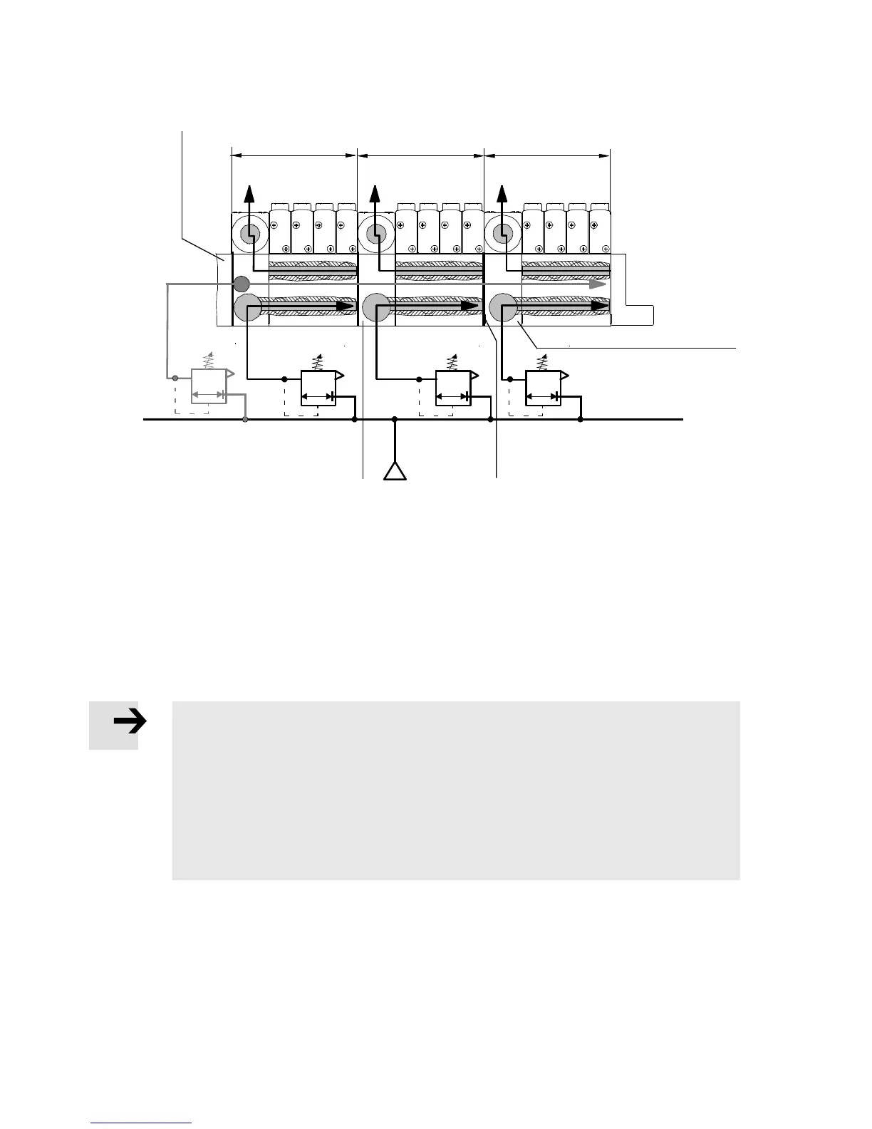
1 Pneumatic interface or multi-pin plug
connect io n plate with supply port (1) for
pressure zone 1 and pilot connection (12/14)
for the total valve terminal
2 Pressure zone 1
3 Pressure zone 2
4 Pressure zone 3
5 Air supply plate for pressure zone 3
6 Identification of the pressure zone
separating seal (projecting flag)
7 Air supply plate for pressure zone 2
Fig. 3.6 Example of an MPA-S valve terminal with 3 pressure zones
3.6.3 Operation of the MPA-S... valve terminal with reversible pressure regulators
Note
Operation of the MPA-S... valve terminal with reversible pressure regulators (Ident.
code PN, PM, PL, PK):
• No 2x 2/2-directional control valves with ident. code D, I and 2x 3/2-directional
control valves with ident. code N, K, H (non-reversible valves) may be ope rated with
these pressure regulators.
• Reversible pressure regulators must not be used on reversibly operated valve ter-
minals.
3.6.4 Setting the pressure regulator
The pressure regulato r plates can be set using the following operator control elements:
– with the adjusting screw for size MPA1
– with the adjusting knob or the adjusting screw for size MPA2.