2Overview
34 Festo – P.BE-MPA-EN – 1309f – English
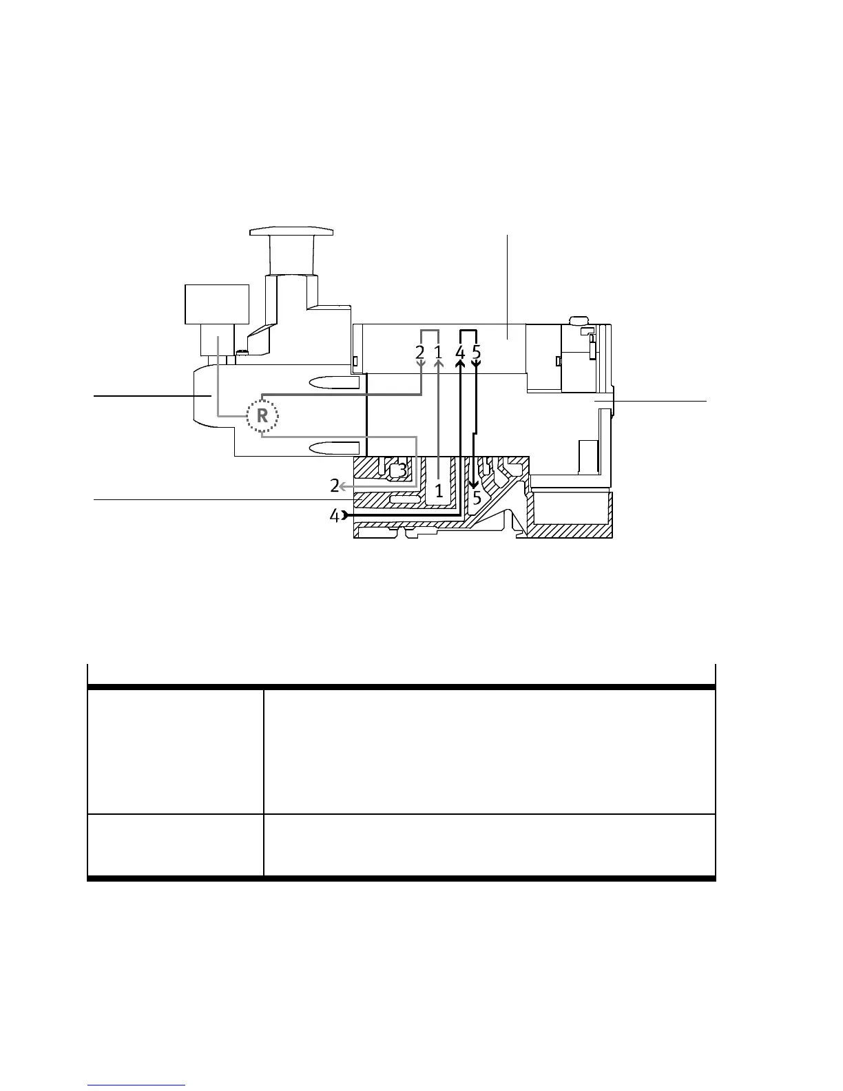
Fig. 2.12 shows the following switching position of the B pressure regulator:
The air is passed from channel (1) through the pressure re gulator plate and the valve to pressure regu-
lator B, where it is regulated and then passed to the port (2) of the sub-base. The unregulated exhaust
air is then fed via channel (4) through th e pressure regulator plat e to the valve and from there to ch an-
nel (5) and exhausted.
1
2
3
4
1 Pressure regulator
2 Valve
3 Intermediate plate
4 Sub-base
Fig. 2.12 B-pressure regulator
Reversible A or B pressure regulator (Ident. code PN, PL, PM, PK)
Pressurizing process The reversible pressure regulator splits up the supply air in channel (1)
and regulates the pressure in front of the valve in the corresponding
channel (( 1 in Tab. 2.15), in the other channel ( 2 in Tab. 2.15)
the unregulated pressure from channel (1) is present. The reg ulated air
is then switched to the corresponding work channel. The valve is thus
operated in reversible mode.
Exhaust process In the valve, the exhaust flows from the c orresponding work channel
( 3 in Tab. 2.15) to channel (1) and is guided in the pressure
regulator plate to the corresponding exhaust channel of the sub-base .
Tab. 2.14 Reversible A or B pressure regulator