3 Mounting and installation
Festo – P.BE-MPA-E N – 1309f – English 69
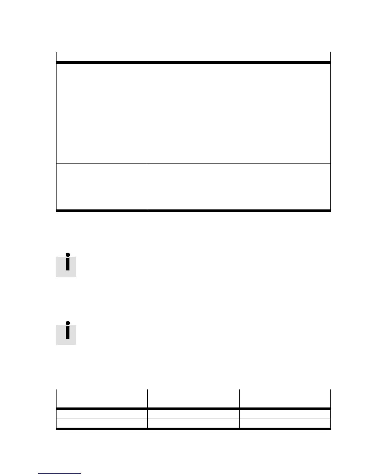
Valve sub-bases
Pressure zone with vacuum or
low pressure supply via
connection (1)
1) 2)
The pressure zone must be equipped only with the following valve
sub-bases:
– 5/2-directional control valve, monostable (ident. code M, MS,
MU)
– 5/2-way bistable valve (ident. code J)
– 5/3-directional control valves (ident. c odes B, E and G)
– 2x 3/2-directional control valves ( ident. code HS, HU, KS, KU
and NS)
– 3/2-directional control valve ( ident. code W and X) see also the
subsequent note
– 2x 2/2-directional control valve ( ident. code DS )
Pressure zone with excess
pressure supply
3)
via port ( 1)
The pressure zone can be equipped additionally with the following
valve sub-bases:
– 2x 3/2-directional control valves ( ident. code H, K and N)
– 2x 2/2-directional control valves ( ident. code D and I), see also
subsequent footnote
1) The valve sub-bases with Ident. codes D, H, K, N and I are not resistant to vacuum or low pressure if they are supplied via connec-
tion (1)!
2) Pilot pressure diagram Appendix A, Fig. A.3
3) Pilot pressure diagram Appendix A, Fig. A.1
Tab. 3.6 Valve sub-bases
Valve with ident. code I, 2x 2/2-directional c ontrol valves:
– With this valve, vacuum is supplied at connection (5). Solenoid coil 14 switches t he
vacuum to connection (4).
– The opera ting pressure at port (1) can be used as an ejector pulse at port (2). The
operating pressure is switched to port (2) with solenoid coil 12. If the MPA-S valve
terminal is also equipped with other valves, operate this valve in a separate pressure
zone with separated exhaust duct (5 ).
Valves with ident. code W and X, 3/2-directional control valve:
– These valves can be supplied individually and therefore operated in t he entire pres-
sure range from –0.9 ... 10 bar. They are independent of supply connection (1) of the
valve terminal. The connections through which these valves are supplied with com-
pressed air or vacuum and through which exhaust air is removed are shown in
Tab. 3.7.
The pilot air is supplied through the valve terminal.
3/2-directional control valve
Compressed air or vacuum via
connection
Exhaust air through port
Ident. code X (4) (3)
Ident. code W (2) (5)
Tab. 3.7 Connections to v alves with ident. code X and W
 Loading...


