3 Mounting and installation
Festo – P.BE-MPA-E N – 1309f – English 75
Note
Damage to components and malfunctions!
• Please observe,
– that with MPA-S valve terminals with more t han 8 sub-bases, an elec tric supply plate
is required for supplemental supply of load voltage.
– to the right of the electrical air supply plate, only electronics modules with separ-
ated circuits of type VMPA..-FB-EMG-.... are permitted ( also section 5.3.6). If your
MPA-S valve terminal is only equipped with electronic modules with a common cir-
cuit ( type VMPA...-FB-EMS-...), then you c an supply the pneumatics as follows:
– for valve terminals with CPX terminal: exclusively via an interlinking block with
4-pin system supply, type CPX-GE-EV-S or CPX-GE-EV-S-7/8-4POL of the CPX
terminal.
– forvalveterminalswithCPIinterface:throughtheCPIinterfaceoftypeVMPA-CPI.
– that the electric supply plate must not be installed directly to th e left of a pneumatic
air supply plate (type VMPA1-FB-SP…).
– that you do not touch the electrostatically sensitive contact surfaces of the plug
connect ors on the side of the electric supply plate.
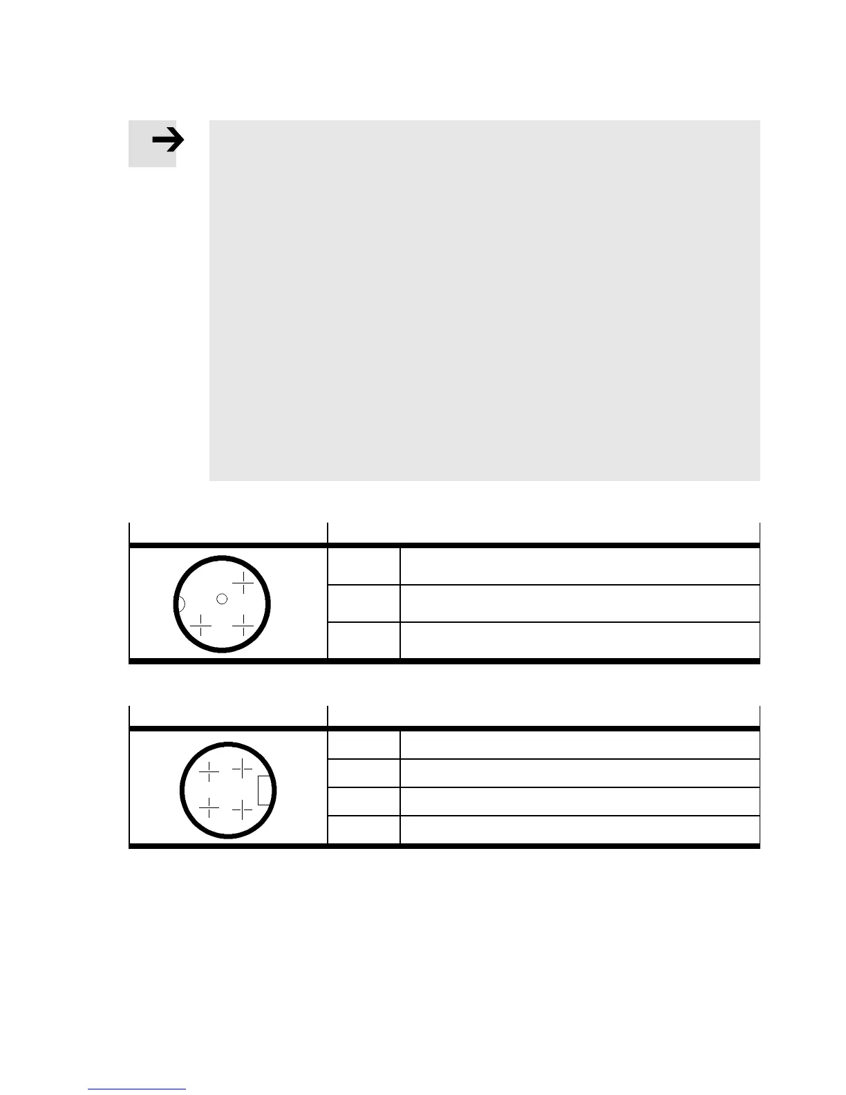
Connect the corresponding electrical air supply plate as shown in subsequent tables:
M18 plug
Pin allocation
2
34
Pin 2 24 V DC valves
Pin 3 0VDCvalves
Pin 4 Functional earth
Tab. 3.10 Pin assignment of the electric air supply plate type VMPA -FB-S P-V
7/8” plug, (4-pin)
Pin allocation
A
B
D
C
Pin A Not connected
Pin B 24 V DC valves
Pin C Functional ear th
Pin D 0VDCvalves
Tab. 3.11 Pin assignment of the elec t ric air supply plate type VMPA-FB-S P-7/8-V-4POL