SECTION 4 – SYSTEM INSTALLATION
Page 14 of 21 Fike Clean Agent System w/ FM-200™ UL / ULC Ex4623
Revision Date: January, 2010 Manual P/N: 06-215 (Rev G) FM 3010715
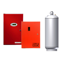
4.5.1 360° NOZZLES
360
o
Nozzles should be located in a symmetrical, or near symmetrical, pattern within the protected area. 360
o
Nozzles should be located near the area centerline – discharging toward the perimeter and/or other nozzles.
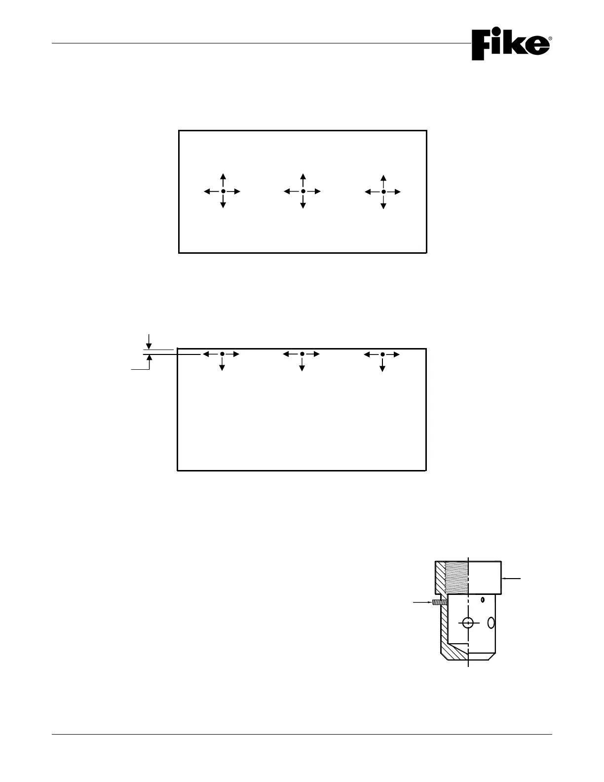
4.5.2 180° NOZZLES
180° Nozzles should be located in a symmetrical, or near symmetrical, pattern within the protected area. 180
o
Nozzles should be located along the perimeter of the area – discharging along the perimeter and toward the
opposite side. These nozzles can be located a maximum of 1’-0” (0.3 m) out from the wall.
NOTE: 180° Nozzles can also be installed in back to back applications. Maximum distance between nozzles
is 1’-0” (0.3 m) as shown in the illustration on page 15 of 48, Section 2 / Design.
4.5.3 NOZZLE SET SCREW INSTALLATION
WARNING: Verify the Set Screws found on the side of the
nozzle are in place after system installation. Failure
to have the setscrews in place will affect agent
distribution and possibly the system’s ability to
suppress the fire.
INSIDE WALL
SET SCREWS TO
BE FLUSH WITH
NOZZLE
1.0’ (0.3 m)
Maximum