SECTION 2 – DESIGN
Page 14 of 39 Fike Clean Agent System w/ FM-200™ UL / ULC Ex4623
Revision Date: January, 2010 Manual P/N: 06-215 (Rev G) FM 3010715
Example no.1: A system supplying 1,300 lbs. has a system flow rate requirement of 130 lbs./sec. (1,300 lbs. ÷
10 sec. = 130 lbs./sec.). Refer to the Nozzle Flow Rate Table. The highest possible flow rate for any nozzle size
is 33 lbs./sec. Therefore, a minimum of four (4) 2” NPT nozzles will be required.
Example no. 2
: A system supplying 590 kg has a system flow rate requirement of 59 kg/sec. (590 kg ÷ 10 sec. =
59 kg/sec.). Refer to the Nozzle Flow Rate Table. The highest possible flow rate for any nozzle size is 14.97
kg/sec. Therefore, a minimum of four (4) 50 mm nozzles will be required.
NOTE: A maximum nozzle flow rate of 17 lbs./sec. (7.7 kg/sec.) is recommended for all areas with false ceilings
or delicate operations where a higher flow rate may dislodge objects or affect a process.
2.7.2.1 ENGINEERED NOZZLES
The minimum orifice area that can be utilized for a 180
o
or a 360
o
Engineered System Nozzle is twenty percent of
the pipe cross sectional area. The maximum orifice area that can be utilized must be less than eighty percent of
the pipe cross sectional area. Therefore, a computerized flow calculation program is used to select the proper
nozzles to meet the orifice size limitations, as well as the minimum pressure requirement of 55 psig (3.8 bar).
WARNING: System installation SHALL NOT begin until the final design of the piping network has been
verified using Fike’s Engineered Flow Calculation.
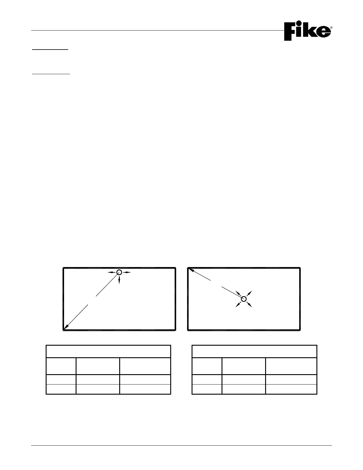
2.7.3 NOZZLE AREA COVERAGE
Nozzle Area Coverage must also be considered when designing a Fike HFC-227ea System. Each nozzle type
(180
o
or 360
o
) has been UL Listed and FM approved for the maximum area coverage limitations listed below. The
maximum area coverage is expressed as a radius (“R”) of coverage along the discharge axis for both nozzle
types. Nozzle area coverage values are the same for Pre-Engineered and Engineered Nozzles.
Both nozzle types can be located a maximum of one (1) ft. (0.3 m) below the ceiling (or highest point of protection
when stacking nozzles). Additionally, 180
o
Nozzles can be placed a maximum of one (1) ft. (0.3 m) away from the
sidewall.
NOZZLE AREA COVERAGE (ENGLISH) NOZZLE AREA COVERAGE (METRIC)
Nozzle
Type
Radius “R”
Dimension
Ceiling Height
Range
Nozzle
Type
Radius “R”
Dimension
Ceiling Height
Range
180
o
45’-8” 12 in. to 16 ft. 180
o
13.92 m 0.3 to 4.88 m
360
o
29’-8” 12 in. to 16 ft. 360
o
9.04 m 0.3 to 4.88 m
R
180° NOZZLE 360° NOZZLE
R