SECTION 1 – EQUIPMENT
UL / ULC Ex4623 Fike Clean Agent System w/ FM-200™ Page 23 of 25
FM 3010715 Manual P/N: 06-215 (Rev G) Revision Date: January, 2010
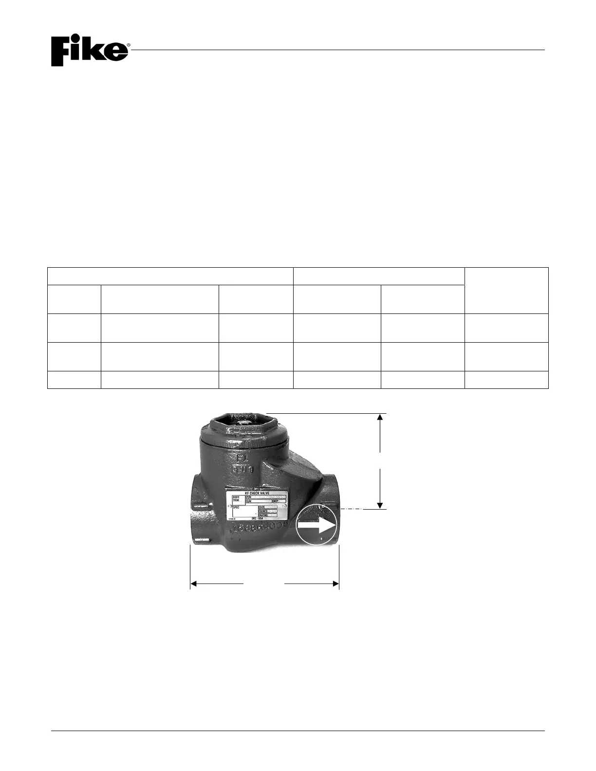
1.11 CHECK VALVES
Check Valves are required for all HFC-227ea Containers connected in a manifold arrangement. NFPA 2001,
Section 2-1.3.5 requires all containers connected to a manifold have an automatic, mechanical, means of
preventing agent loss from an open leg of a manifold if the system is activated while a container is removed for
maintenance. Therefore, the Check Valves are required for each container in a manifold arrangement.
1” NPT (25 mm) Check Valves (P/N 02-2980) are used for manifold arrangements, including connected
main-to-reserve systems, that utilize Small Capacity HFC-227ea Containers with the 1” (25 mm)
Discharge Outlet Valve.
2” NPT (50 mm) Check Valves (P/N 02-4158) are used for manifold arrangements, including connected
main-to-reserve systems, that utilize Inverted HFC-227ea Containers with the 2-1/2” (65 mm) Discharge
Outlet Valve.
3” NPT (80 mm) Check Valves (P/N 02-4157) are used for manifold arrangements, including connected
main-to-reserve systems, that utilize Large Capacity HFC-227ea Containers with the 3” (80 mm)
Discharge Outlet Valve.
Check Valve Data Dimensions
Part No. Description
Equivalent
Length
Height Length
Approximate
Weight
02-2980 1” (25 mm) Check Valve 2 ft. (0.61 m)
3-3/4” (95 mm)
(maximum)
4-1/4” (108 mm) 9 lbs. (4.1 kg)
02-4158 2” (50 mm) Check Valve 4 ft. (1.22 m)
4-1/2” (114 mm)
(maximum)
6” (152 mm) 12 lbs. (5.4 kg)
02-4157 3” (80 mm) Check Valve 4 ft. (1.22 m) 6” (152 mm) 8” (203 mm) 31 lbs. (14.1 kg)
Len
th
Hei
ht
Flow Direction