Do you have a question about the Fike Clean Agent System and is the answer not in the manual?
Details about the extinguishing agent HFC-227ea, its properties and safety.
Explains the agent's fire extinguishing mechanism and performance characteristics.
Lists chemical, physical, and safety properties of HFC-227ea.
Outlines system design, installation, and usage requirements and restrictions.
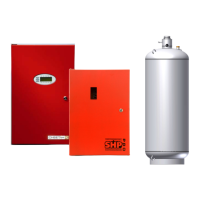
Describes the steel pressure vessels used for agent storage, including types and specifications.
Lists standard items provided with Fike HFC-227ea containers, such as nameplates and siphon tubes.
Details the GCA's function as an electrically activated discharge device for container valves.
Lists optional components for HFC-227ea containers like liquid level indicators and low pressure switches.
Explains the part number structure for ordering Fike HFC-227ea containers and their options.
Describes the devices that control agent flow and distribution, including types and specifications.
Explains the requirement for check valves in manifold arrangements to prevent agent loss.
Lists signs to comply with NFPA 2001 and inform personnel about system status and hazards.
Covers control panels and manual actuators for Fike systems.
Guides on identifying hazard types (Class A, B, C) for system design.
Provides guidelines for determining the proper agent concentration based on hazard type and activation.
Safety recommendations for occupied and non-occupied spaces based on exposure limits.
Steps to determine the amount of HFC-227ea agent needed, including volume and temperature calculations.
Discusses different piping distribution methods (Pre-Engineered, Engineered, Modular, Central Storage).
Factors influencing container selection based on agent quantity, fill ranges, and system type.
Factors determining nozzle selection based on flow rate, area coverage, and placement.
Covers limitations for engineered system piping, including tee splits, elevation, and orientation.
Discusses physical limitations like agent in pipe percentage and first tee location in engineered systems.
Details manifold configurations for connecting multiple containers, including types and dimensions.
Outlines design and installation procedures for pre-tested systems, including piping layout and pipe sizing.
First step in designing a system: determine hazard area and volume for each enclosure.
Calculates the amount of agent needed for each hazard area based on volume and concentration.
Outlines container selection and nozzle requirements for the sample system based on calculations.
Describes routing pipe networks and container locations on a scaled plan view.
Demonstrates the process of performing a flow calculation using software output.
Provides procedures for correct installation and mounting of containers in vertical and horizontal positions.
Details how discharge piping connects to container valves using unions, couplings, and manifolds.
Explains the use of discharge manifolds for connecting multiple containers into a common supply network.
Specifies acceptable piping and fitting materials (Schedule 40/80, threaded, welded, grooved) according to NFPA 2001.
Procedures for mounting and orienting discharge nozzles, including placement and set screw installation.
Covers installation procedures for GCA and ARM components, including electrical connections.
Illustrates electrical connections for GCA and ARM modules to the control system.
Details the low pressure switch, its specifications, and installation connections.
Checks aspects of the hazard area like configuration, leakage, and enclosure integrity.
Checks container and bracket security, mounting position, and pressure gauges.
Checks discharge piping support, joint tightness, and pressure testing.
Verifies nozzle installation, orientation, and clear discharge path, checking for obstructions.
Verifies operation of auxiliary functions like door closures, damper closures, and air handling shutdown.
Maintenance checks for discharge piping for corrosion, damage, and support integrity every six months and annually.
Maintenance checks for discharge nozzles every six months, ensuring clarity, aim, and correct part numbers.
Maintenance checks for container pressure and leaks every three months, referencing pressure vs. temperature table.
Maintenance checks for GCA leads and wiring every six months and replacement every ten years.
Procedures for container retesting (every 5 years) and visual inspection according to regulations.
Procedures for replacing or adding pressure gauges and low pressure switches, including precautions.
Tables showing container dimensions, part numbers, fill ranges, and weights.
| Brand | Fike |
|---|---|
| Model | Clean Agent System |
| Category | Laboratory Equipment |
| Language | English |