SECTION 2 – DESIGN
UL / ULC Ex4623 Fike Clean Agent System w/ FM-200™ Page 15 of 39
FM 3010715 Manual P/N: 06-215 (Rev G) Revision Date: January. 2010
“R”
“R”
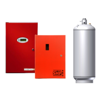
2.7.4 NOZZLE PLACEMENT
Nozzles should be located in a symmetrical or near symmetrical pattern within the protected area. 360
o
Nozzles
are designed to be located on, or near, the centerline of the protected area, discharging toward the perimeter of
the area being covered. The system designer should layout the nozzles on a floorplan and verify that the entire
area being protected is adequately covered without any “blind spots” due to nozzle locations.
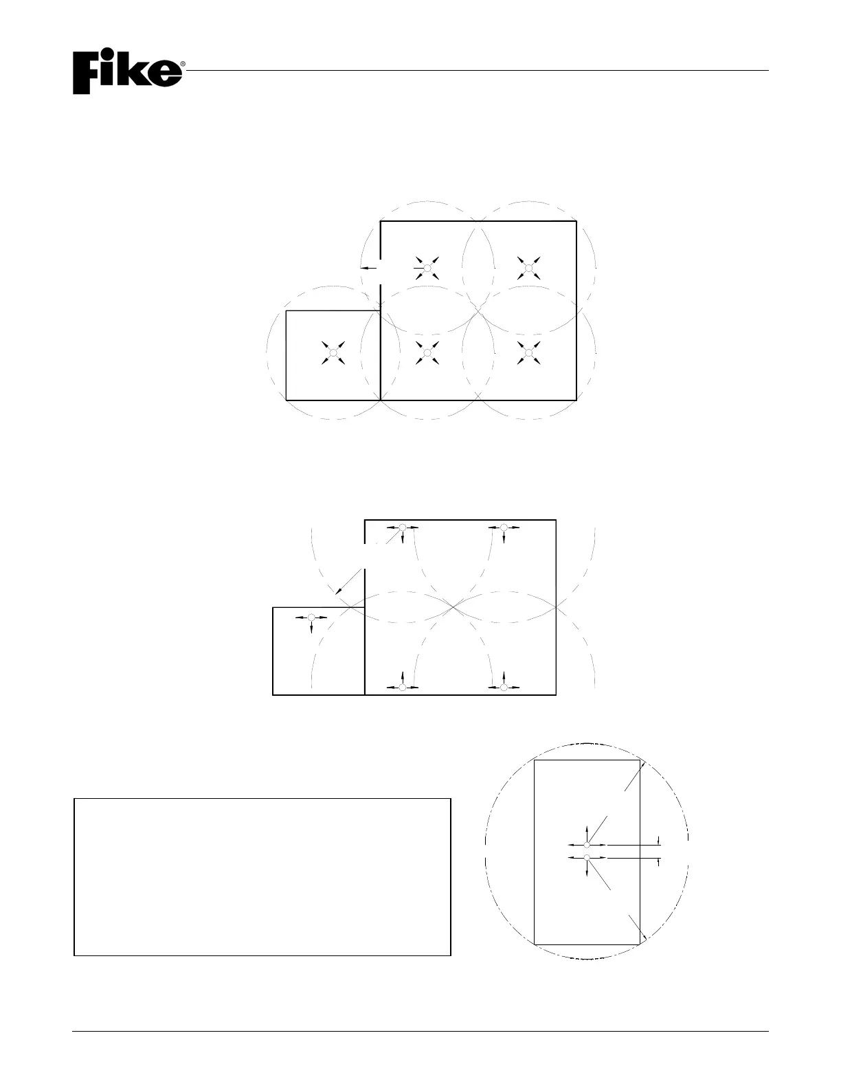
180
o
Nozzles are designed to be located along the perimeter of the area, discharging toward the opposite side as
shown below. These nozzles MUST be located no farther than 1’-0” (0.3 m) away from the wall.
180
o
Nozzles can also be installed in back to back applications. Maximum distance between nozzles is
approximately 1’-0” (0.3 m) as shown in the following illustration.
The use of 180
o
nozzles in a back to back application
is U.L. listed, and not listed by FM Approvals.
NOTE: All discharge nozzles may be located a maximum of 1’-0” (0.3 m) below the ceiling.
Approx. 1’-0” (0.3 m)
“R”
“R”
IMPORTANT NOTE:
The Minimum Piping Distance Rule outlined in Section
2.8.5 does not apply when using back-to-back 180º
nozzles as long as:
1) Agent supplied and flow rate from both nozzles
are the same.
2) Pipe size from tee to both nozzles is the same.
3) Pipe lengths from tee to each nozzle are within
10% of each other.