SECTION 3 – SAMPLE PROBLEM
UL / ULC Ex4623 Fike Clean Agent System w/ FM-200™ Page 1 of 17
FM 3010715 Manual P/N: 06-215 (Rev G) Revision Date: January, 2010
This section is intended to illustrate a step by step procedure for designing a Fike HFC-227ea system. The
sample system will be designed to comply with the guidelines and limitations discussed in the previous sections.
For detailed instructions, consult Fike's HFC-227ea Engineered System Flow Calculation Program manual for the
use and operation of the program.
The following example consists of a computer room, U.P.S. room and operations room with a common sub-floor.
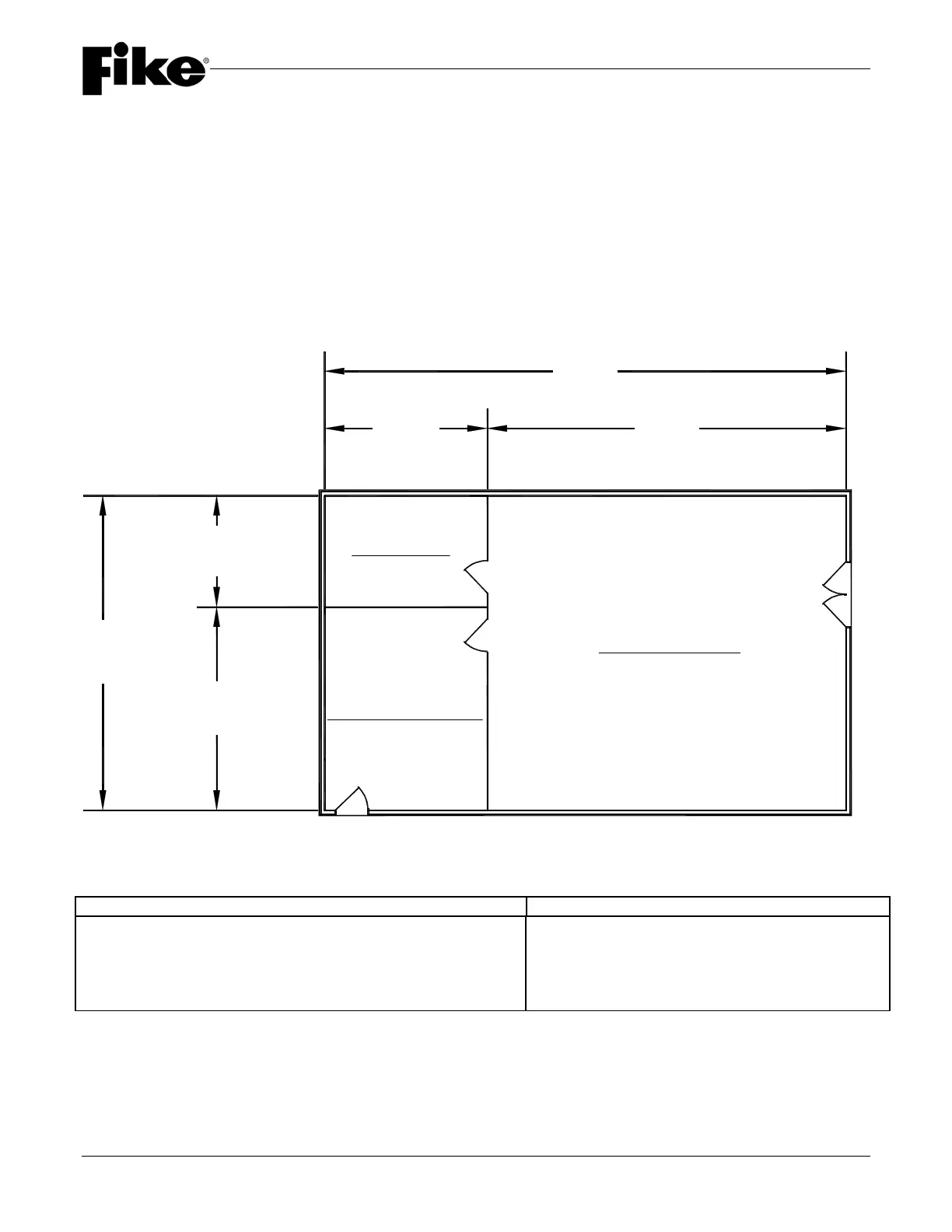
3.1 DETERMINE HAZARD VOLUME
The first step is to determine the hazard area and volume for each enclosure involved. Refer to Figure 3.1 for
details.
FIGURE 3.1
English Values Metric Units
Computer Rm: 29.0 x 33.0 = 957 sf x 9.0 = 8613.0 cf 8.84 x 10.06 = 88.93 m
2
x 2.743 = 243.86m
3
UPS Room: 10.00 x 15.0 = 150 sf x 9.0 = 1350.0 cf 3.05 x 4.57 = 13.94 m
2
x 2.743 = 38.22 m
3
Operations Room: 14.0 x 15.0 = 210 sf x 9.0 = 1890.0 cf 4.27 x 4.57 = 19.51 m
2
x 2.743 = 53.51 m
3
Sub-Floor: 29.0 x 48.0 = 1393 sf x 1.2 = 1670.4 cf 8.84 x 14.63 = 129.33 m
2
x 0.381 = 47.30 m
3
29'-0"
(8.84 m)
10'-0"
(3.05 m)
19'-0"
(5.79 m)
15'-0"
(4.57 m)
33'-0"
(10.06 m)
48'-0"
(14.63 m)
U.P.S. ROOM
OPERATIONS ROOM
COMPUTER ROOM
(w/ Common Subfloor)