SECTION 2 – DESIGN
Page 18 of 39 Fike Clean Agent System w/ FM-200™ UL / ULC Ex4623
Revision Date: January, 2010 Manual P/N: 06-215 (Rev G) FM 3010715
2.8 PIPING NETWORK LIMITATIONS (ENGINEERED SYSTEMS)
This section will cover the piping limitations that apply to all Fike Engineered HFC-227ea system configurations.
This information is intended to give the system designer the information necessary to complete a preliminary
piping layout. The following limitations define the parameters that have been verified through testing, but
installation SHALL NOT begin until the design has been verified using Fike’s Engineered HFC-227ea Flow
Calculation Program. For program details, refer to the HFC-227ea Flow Calculation User’s Manual, P/N 06-208.
2.8.1 TEE SPLIT RATIOS
The Fike Engineered HFC-227ea System has been tested to define the maximum degree of imbalance that can
be predicted at tee splits. This value has been expressed in terms of a split ratio of one outlet branch versus the
other. Each ratio indicated is referring to a percentage of the total incoming flow.
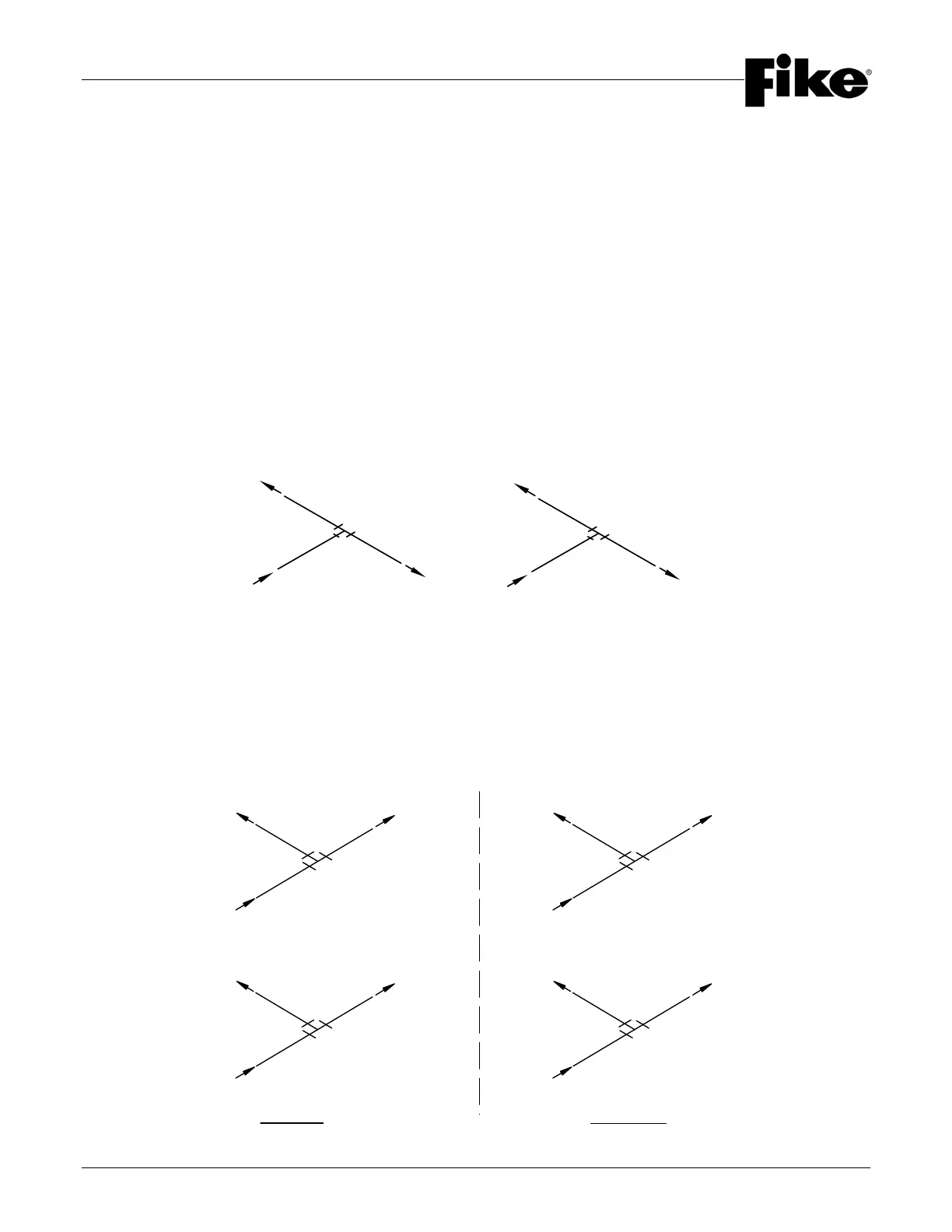
2.8.1.1 BULLHEAD TEE
A Bullhead Tee is defined as a tee configuration where the two outlet branches change direction from the
incoming piping inlet. See the diagram below for further clarification.
The split ratio range for a Bullhead Tee is 75:25 to 50:50. This means that the major-flow outlet has an
acceptable range of 50% minimum to 75% maximum, and the minor-flow outlet has an acceptable range of 25%
minimum to 50% maximum. These figures are determined as percentages of the total incoming flow amount
through the tee. See the diagram below for further clarification.
2.8.1.2 SIDE-THRU TEE
A Side-Thru Tee is defined as a tee configuration where one outlet branch changes direction from the inlet, and
the other continues straight through in the same direction as the inlet. See the diagram below for further
clarification.
The split ratio range for a Side-Thru Tee is 90:10 to 75:25. This means that the major-flow outlet (the thru branch)
has an acceptable range of 75% minimum to 90% maximum, and the minor-flow outlet (the side branch) has an
acceptable range of 10% minimum to 25% maximum. These figures are determined as percentages of the total
incoming flow amount through the tee. See the diagram below for further clarification.
50% OUT
50% OUT
100% IN 100% IN
25% OUT
75% OUT
10% OUT
100% IN
90% OUT
90% OUT
10% OUT
69% OUT31% OUT
100% IN
100% IN
100% IN
INCORRECTCORRECT
25% OUT
75% OUT