SECTION 4 – SYSTEM INSTALLATION
UL / ULC Ex4623 Fike Clean Agent System w/ FM-200™ Page 15 of 21
FM 3010715 Manual P/N: 06-215 (Rev G) Revision Date: January, 2010
4.6 GAS CARTRIDGE ACTUATOR (GCA) / AGENT RELEASE MODULE (ARM)
The GCA/ARM installation and electrical connection should be the last items completed before the system is
placed into operation. The following sections show the standard hardware required and the procedures
necessary to complete this part of the installation.
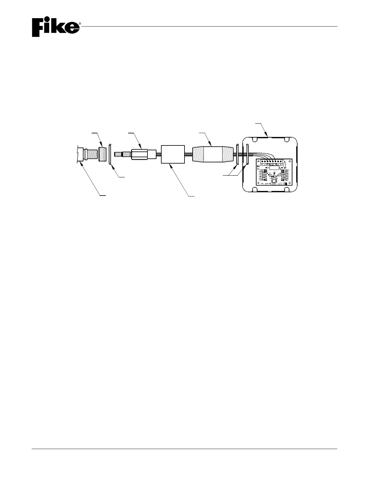
4.6.1 2-1/2” (65 mm) VALVE (INVERTED CONTAINER) GCA INSTALLATION
The following components are provided with all Inverted containers. Use the following procedure to install the
GCA and ARM for these containers. The electrical hardware (conduit, junction box, etc.) can be changed to suit
special conditions or customer preference as needed.
1. Install the 1” x 1/2” (25mm x 15mm) conduit reducing bushing on the Container Actuator Boss. Assemble
a 1” (25mm) locknut on the conduit bushing.
2. Insert the GCA into the Actuator Boss and tighten to approximately 50-90 inch-pounds. Unwrap and straighten
the GCA leads. Be certain that the lead ends are shunted together. Remove all bends, twists and/or kinks
from
the wires. Do not remove shunts.
3. Install the 1” (25mm) coupling with the nipple attached onto the bushing, allowing the GCA leads to pass
through the grouping. Tighten the coupling/nipple to the locknut. The face of the bushing and locknut
assembly should be flush with the face end of coupling.
4. Install a second locknut to the open end of the nipple. Remove the knockout blank from upper left side of the
4-11/16” (120 mm) square conduit box. Pass the GCA leads through the knockout hole and install the
assembly to the box using the third locknut, which is inserted from the inside of the box. Align the box and
tighten securely.
5. Install ARM in the lower right corner of the box using the adhesive strips provided on the back.
4-11/16" SQ.
ELECTRICAL BOX
LOCKNUT
CONDUIT
COUPLING
REDUCING
BUSHING
CONTAINER
ACTUATOR BOSS
LOCKNUT
GCA
ELEC. NIPPLE
ARM