SECTION 4 – SYSTEM INSTALLATION
UL / ULC Ex4623 Fike Clean Agent System w/ FM-200™ Page 1 of 21
FM 3010715 Manual P/N: 06-215 (Rev G) Revision Date: January, 2010
The system installation must comply with the requirements of this manual; NFPA 2001, latest edition; all
applicable local codes, regulations, and standards and the authority having jurisdiction (AHJ).
4.1 AGENT STORAGE CONTAINERS
The following sections provide pictorial clarification and procedures for the correct installation and mounting
positions of Fike containers and associated hardware.
Make certain that each container has been installed in the correct location. Each container should have a
nameplate with an identifying part number. Check the container part number against those listed on the system
plans to verify their locations.
Containers should be located in clean, dry, and relatively vibration-free areas. Avoid aisleways and other high
traffic areas where physical damage or tampering is more likely. Containers should never be mounted where the
container could potentially be splashed with, or submerged in any liquid.
Container brackets must be mounted securely to solid load-bearing surfaces that will support the container load.
Some installations may require additional mounting support not supplied by Fike.
WARNING: The Gas Cartridge Actuator (GCA) should always be the last component installed on a Fike
Clean Agent system.
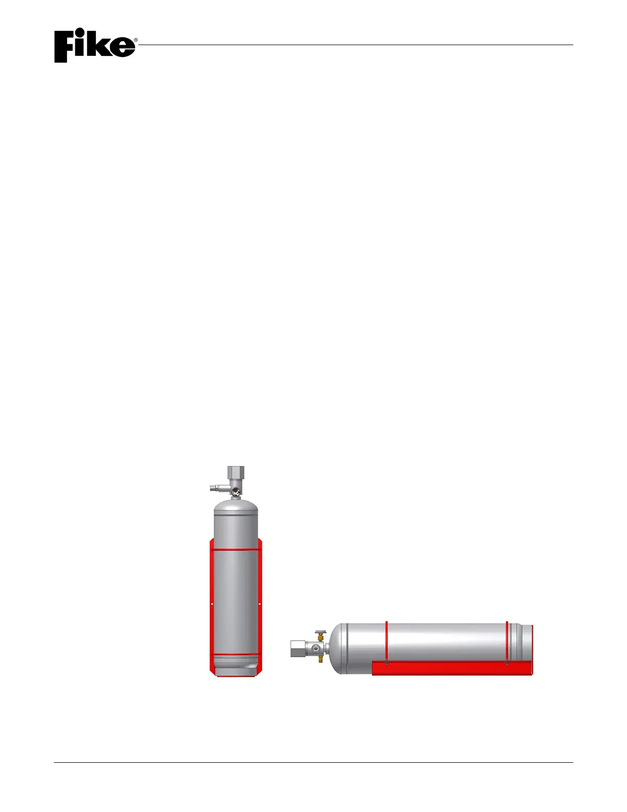
4.1.1 MOUNTING DETAILS FOR VERTICAL / HORIZONTAL CONTAINERS
20 – 60 lb. (8 – 27 L) Containers are supplied with mounting brackets that must be secured to a solid, load-
bearing surface using a minimum of four fasteners. As an option, the brackets may be welded into place. These
containers can be mounted in the following configurations:
• Floor or wall mounted in the vertical (valve up) position
• Floor mounted in the horizontal (pressure gauge up) position
CAUTION: These containers have siphon tubes. DO NOT mount the containers in the inverted (valve down)
position. Failure to comply with this requirement will result in an incomplete discharge.
Vertical (Upright) Horizontal Floor