SECTION 4 – SYSTEM INSTALLATION
UL / ULC Ex4623 Fike Clean Agent System w/ FM-200™ Page 19 of 21
FM 3010715 Manual P/N: 06-215 (Rev G) Revision Date: January, 2010
4.7.2 GAS CARTRIDGE ACTUATOR (GCA) INSTALLATION PROCEDURE
After the electrical and control systems have been checked out, proceed with the gas cartridge actuator installation
as follows.
Step 1: Move the “armed/disabled” switch on the control panel to the “disabled” position.
Step 2: Wait a minimum of 10 minutes to allow capacitors on agent release modules to dissipate their electrical
charge.
Step 3: Stretch all the leads and find the proper length required for the installation. Remember to allow extra
length for the possibility of servicing the system and the need to shunt in the future. However, do not
allow a quantity that will not safely store within the space provided within the ARM box.
Step 4: With shunts intact, strip about 1/2" (15mm) of insulation from the red and the blue lead, but keep the
shunt intact. In the middle of the stripped portion, use small pliers to fold the wires in half and crimp.
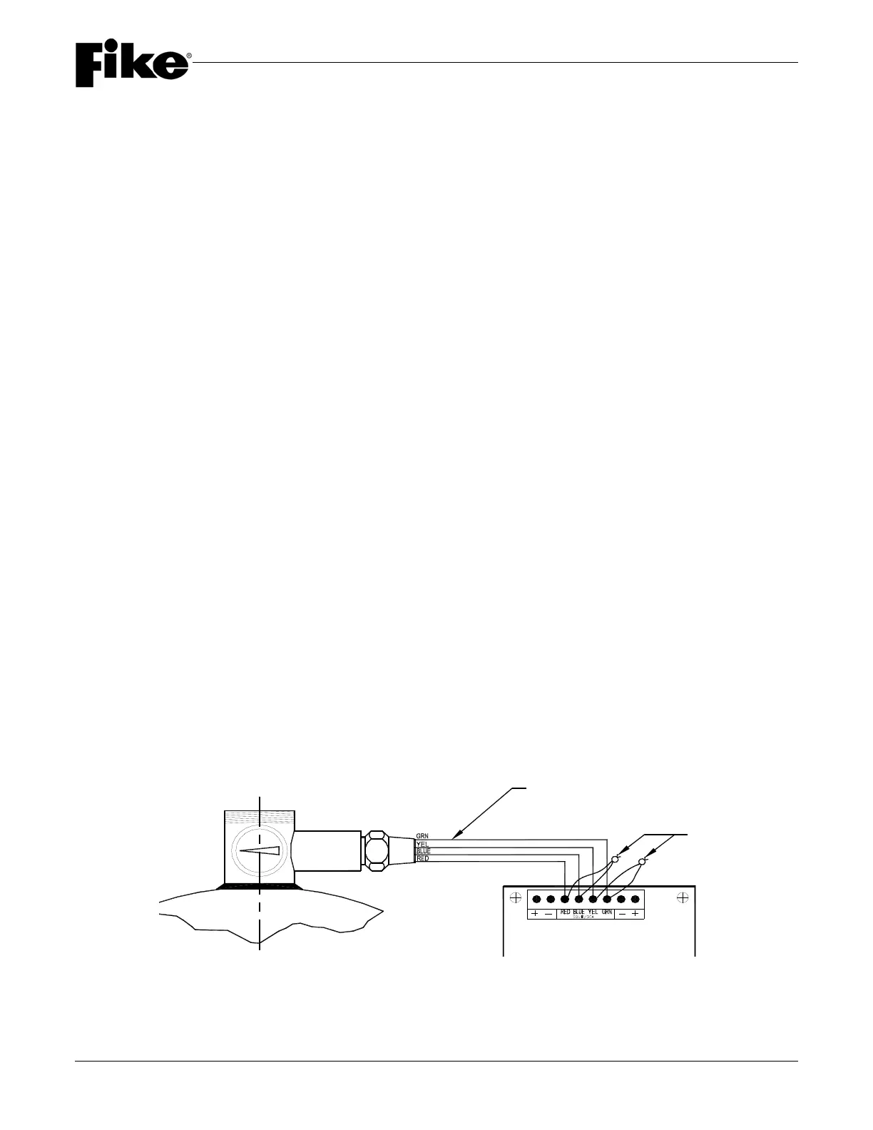
Step 5: Insert the stripped sections of the gas cartridge actuator’s red and blue leads under their respective
screws on the terminal of the agent release module and tighten each screw. For ARM Rev.1, use the
center two terminals. For Fike ARM III, terminate the yellow and green leads in the same manner as the
red and blue leads. The yellow and green terminals are shunted internally and connection to these
terminals provides safety for this pair. DO NOT use these terminals for the red and blue leads. (See
figure below)
Step 6: Repeat steps 3 through 5 for all containers in the system.
Step 7: Remove the shunts from the pigtails and isolate each wire. If the wire ends are exposed, cover with
electrical tape and secure against ground faults. These pigtails can be used at a later date to recreate a
shunt and safely remove the wires from the ARM when servicing the system. Install covers on all
electrical
boxes.
Step 8: Check the control panel for any trouble indication, other than the one caused by the “disable” position of
the “armed/disabled” switch.
WARNING: DO NOT ARM THE SYSTEM IF A GROUND FAULT INDICATION IS PRESENT.
Step 9: If no other trouble condition exist, move the “armed/disabled” switch to the “armed” position and reset the
control panel.
WARNING: The Container(s) is/are “NOW ARMED”
GAS CARTRIDGE
ACTUATOR LEADS
ARM
SHUNTS