SECTION 1 – EQUIPMENT
Page 24 of 25 Fike Clean Agent System w/ FM-200™ UL / ULC Ex4623
Revision Date: January, 2010 Manual P/N: 06-215 (Rev G) FM 3010715
1.12 CAUTION / ADVISORY SIGNS
Caution / Advisory Signs are provided to comply with NFPA 2001 requirements, and to provide the necessary
information to personnel in the area.
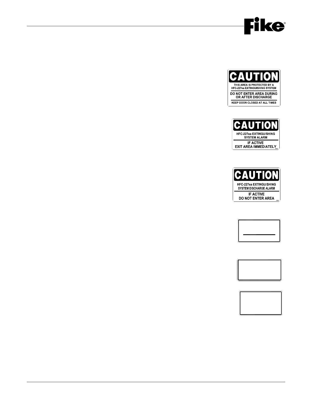
1.12.1 “DO NOT ENTER DURING OR AFTER DISCHARGE” SIGN – (P/N 02-10139)
This sign is provided to alert personnel entering the room that the space is protected
with an HFC-227ea system. It also alerts personnel not to enter the space during or
after a discharge and to keep the doors closed. This sign should be placed on the
outside of every door entering/exiting the protected space. The sign is constructed
from yellow lexan with black lettering. The sign has the following dimensions: 10” x
13” x 1/16” (254 mm x 356 mm x 16 mm). Each sign is adhesive backed for ease of
installation.
1.12.2 “UPON DEVICE ACTIVATION EXIT…” SIGN – (P/N 02-10105)
This sign is provided to explain the presence of notification devices that are located
inside the protected space. This sign explains that the HFC-227ea system will soon
be discharged if the strobe light is flashing, and appropriate actions should be taken.
This sign should be placed at each strobe light location. The sign is constructed from
yellow lexan with black lettering. The sign has the following dimensions: 9” x 6” x
1/16” (229 mm x 153 mm x 16 mm). Each sign is adhesive backed for ease of
installation.
1.12.3 “UPON DEVICE ACTIVATION DO NOT ENTER…” SIGN – (P/N 02-10138)
This sign is provided to explain the presence of notification devices that are located
outside the protected space. This sign explains that the HFC-227ea system has
discharged if the strobe light is flashing, and appropriate actions should be taken.
This sign should be placed at each strobe light location. The sign is constructed from
yellow lexan with black lettering. The sign has the following dimensions: 9” x 6” x
1/16” (229 mm x 153 mm x 16 mm). Each sign is adhesive backed for ease of
installation.
1.12.4 “…SYSTEM ABORT- PUSH AND HOLD” SIGN – (P/N 02-10106)
This sign is provided to explain the presence of the Abort button. This sign should be
placed at each Abort station. The sign is constructed from red lexan with white lettering.
The sign has the following dimensions: 4” x 2-1/4” x 1/16” (102 mm x 51 mm x 16 mm).
Each sign is adhesive backed for ease of installation.
1.12.5 “…SYSTEM RELEASE” SIGN – (P/N 02-10137)
This sign is provided to explain the presence of the Manual Release station. This sign
should be placed at each station. The sign is constructed from red lexan with white
lettering. The sign has the following dimensions: 4” x 2-1/4” x 1/16” (102 mm x 51 mm x
16 mm). Each sign is adhesive backed for ease of installation.
1.12.6 “…SYSTEM MAIN/RESERVE” SIGN – (P/N 02-10107)
This sign is provided to explain the presence of the Main Reserve switch. This sign
should be placed at each switch. The sign is constructed from red lexan with white
lettering. The sign has the following dimensions: 4” x 2-1/4” x 1/16” (102 mm x 51 mm x
16 mm). Each sign is adhesive backed for ease of installation.
HFC-227ea
EXTINGUISHING
PUSH AND HOLD
SYSTEM ABORT
<
Fike PN XX-XXXX
SYSTEM RELEASE
HFC-227ea
EXTINGUISHING
HFC-227ea
SYSTEM
EXTINGUISHING
MAIN / RESERVE
Fike
<
PN XX-XXXX