SECTION 4 – SYSTEM INSTALLATION
UL / ULC Ex4623 Fike Clean Agent System w/ FM-200™ Page 21 of 21
FM 3010715 Manual P/N: 06-215 (Rev G) Revision Date: January, 2010
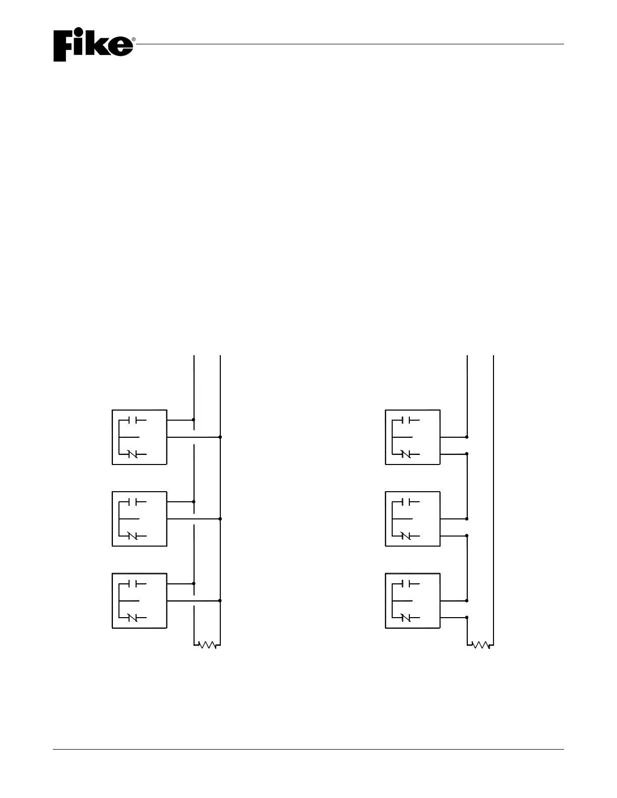
4.8.1 LOW PRESSURE SWITCH WIRING
The Low Pressure Switch can be wired for either of two configurations: normally open or normally closed shelf-
state (de-energized) conditions. When the container is filled and pressurized, the contacts change state. For
example, a normally open switch configuration will be closed when the container is pressurized. If the pressure in
the container drops below 288 psig (196.5 bar kPa), the contact will return to the open (de-energized) position.
The pressure switch should be wired into a supervised circuit in the control panel used to provide a trouble signal
if the container sees a low-pressure condition. The preferred method would be to wire the switch normally open
(closed under pressure).
For applications utilizing a U.L. listed and FMRC approved Cheetah panel, one switch per FRCM (Fast Response
Contact Module) is recommended. Refer to the Installation, Operation & Maintenance Manual for the control
panel being used for specific wiring criteria.
Note:
When the cylinder low pressure switch (p/n 02-9830) is connected to a standard supervisory input circuit, there
will be no distinction between a wiring fault and device actuation. This device is to only be utilized when accepted
by the authority having jurisdiction.
VIOLET
BLUE
N/O
N/C
COM
VIOLET
BLUE
N/C
COM
N/O
VIOLET
BLUE
N/C
COM
N/O
SUPERVISORY
CIRCUIT
N/C
COM
N/O
E.O.L.
BLACK
VIOLET
N/C
COM
N/O
N/C
COM
N/O
BLACK
VIOLET
VIOLET
BLACK
CIRCUIT
SUPERVISORY
E.O.L.