SECTION 2 – DESIGN
Page 26 of 39 Fike Clean Agent System w/ FM-200™ UL / ULC Ex4623
Revision Date: January, 2010 Manual P/N: 06-215 (Rev G) FM 3010715
2.10 MANIFOLD OPTIONS (ENGINEERED SYSTEMS)
Sometimes, a system will require more agent than a single container can provide. In this case, multiple
containers can be connected together via a common manifold arrangement. Main and Reserve supplies of agent
are also connected together in this manner.
Manifolds are assembled using a combination of grooved pipe and grooved fittings, or threaded pipe and fittings
meeting the pressure requirements of NFPA 2001, Section 2. Every container must be the same type, same size,
and identical fill weight in accordance with NFPA 2001, Section 2. 3” NPT (80 mm) Check Valves are required for
EACH container in accordance with NFPA 2001, Section 2.
Manifold assemblies are configured using 3” (80 mm) through 6” (150 mm) pipe sizes, depending upon the
amount of agent being supplied. The common manifold types are as follows:
Center Exit Manifold
End Exit Manifold
Center Exit Manifold / Main and Reserve
End Exit Manifold / Main and Reserve
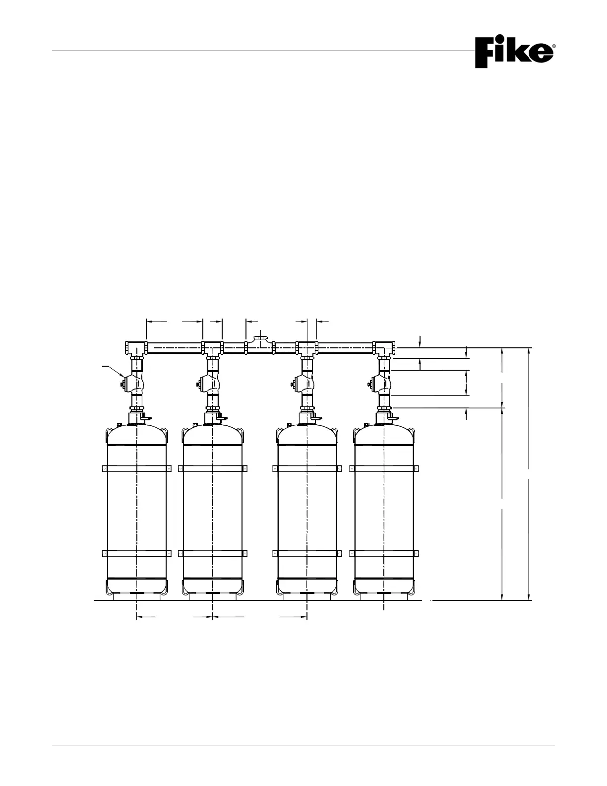
The following diagrams and table show the basic manifold configurations and dimensions. Refer to Section 4 for
additional installation information.
CHECK
VALVE
EE
S S
EE
S
V
EL
CE
l
T
EL
CE
CE
r
30"
(762 mm)
38"
(965 mm)
3" (76 mm)
3" (76 mm)
CENTER EXIT MANIFOLD / 3” THRU 6” (80 mm thru 150 mm)
OR
MAIN & RESERVE MANIFOLD / 3” THRU 6” (80 mm thru 150 mm)