SECTION 4 – SYSTEM INSTALLATION
UL / ULC Ex4623 Fike Clean Agent System w/ FM-200™ Page 17 of 21
FM 3010715 Manual P/N: 06-215 (Rev G) Revision Date: January, 2010
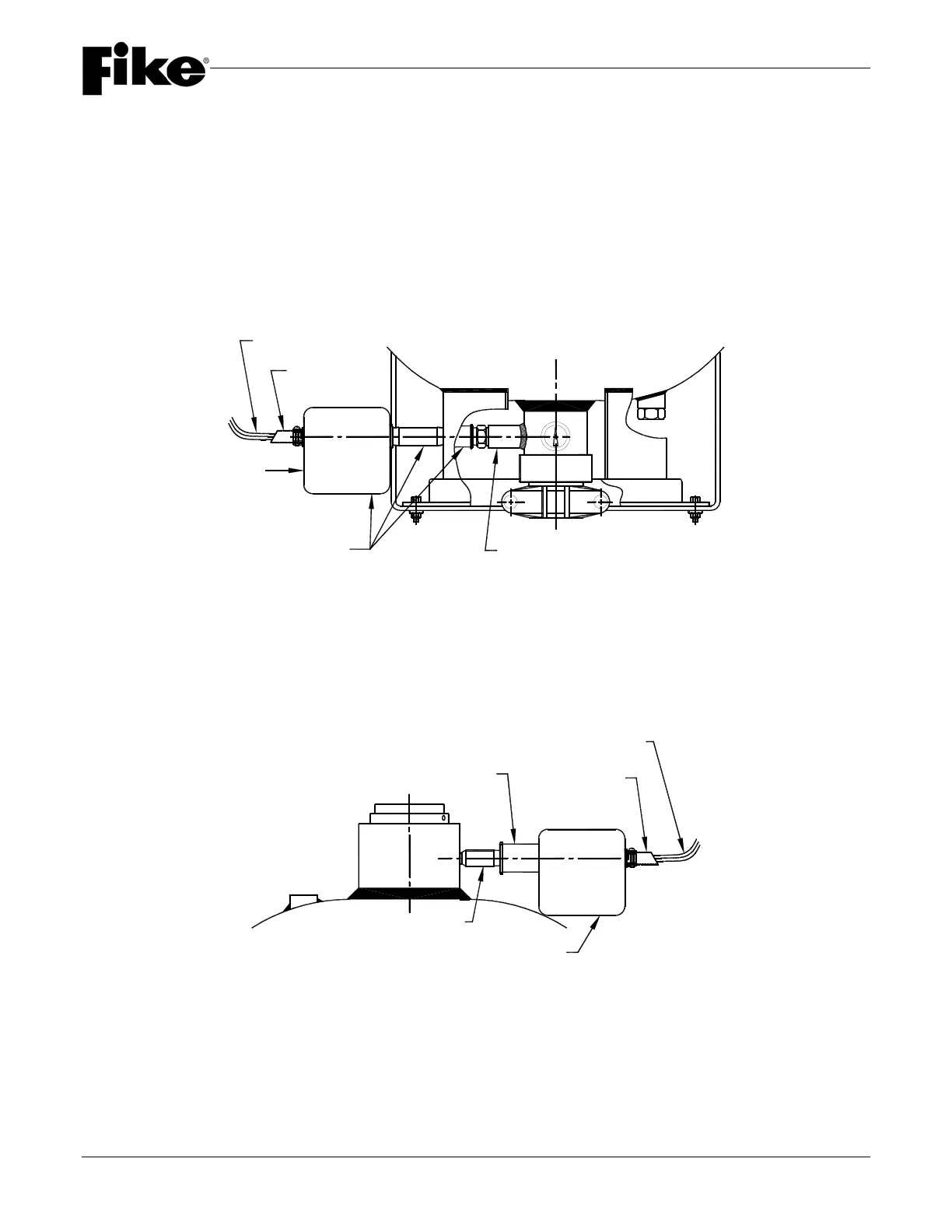
4.7 CONTAINER ELECTRICAL CONNECTIONS
Each container must have an Agent Release Module (ARM). The ARM is mounted in the container junction box
using the adhesive strips located on the back of the module.
Wiring will vary from system to system, depending on the type of control system used. Consult the system plans
and control panel manual for specific wiring information.
ACTUATOR BOSS
CONDUIT
ELECTRICAL BOX
WITH A.R.M. MODULE
G.C.A. WIRE LEADS TO CONTROL SYSTEM
G.C.A./A.R.M. MOUNTING KIT
(P/N 70-1698)
2 1/2" VALVE
ELECTRICAL CONNECTION
G.C.A./A.R.M. MOUNTING
KIT (P/N 70-1697)
ELECTRICAL CONNECTION
ACTUATOR BOSS
ELECTRICAL BOX
WITH A.R.M. MODULE
1" AND 3" VALVE
G.C.A. WIRE LEADS TO CONTROL SYSTEM
CONDUIT