SECTION 4 – SYSTEM INSTALLATION
Page 16 of 21 Fike Clean Agent System w/ FM-200™ UL / ULC Ex4623
Revision Date: January, 2010 Manual P/N: 06-215 (Rev G) FM 3010715
4.6.2 1” (25 mm) and 3” (80 mm) VALVE GCA INSTALLATION
The following components are provided with all containers utilizing 1” & 3” (25 mm & 80 mm) valves. Use the
following procedure to install the GCA and ARM for these containers. The electrical hardware (conduit, junction
box, etc.) can be changed to suit special conditions or customer preference as needed.
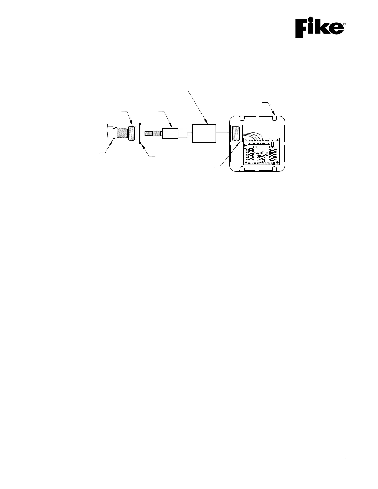
1. Install the 1” x 1/2” (25mm x 15mm) conduit bushing on the Container Actuator Boss. Assemble a 1” (25mm)
locknut on the conduit bushing.
2. Insert the GCA into the Actuator Boss and tighten to 50-90 inch-pounds. Unwrap and straighten the GCA
leads. Be certain that the lead ends are shunted together. Remove all bends, twists and/or kinks from wires.
Do not remove shunts.
3. Install the 1” (25mm) conduit coupling onto the bushing, allowing the GCA leads to pass through the coupling.
Tighten all parts. The face of the bushing and locknut should be flush with the face end of coupling.
4. Remove a 1” (25mm) knockout blank from upper left side of 4-11/16” (120mm) square box. Pass the leads
through the knockout hole. Now pass the leads through the chase nipple, make sure the threaded end is
facing GCA.
5. Secure the chase nipple to the coupling by passing through the knockout hole in the box. Tighten securely,
after aligning the box in an accessible position.
6. Install ARM in the lower right corner of box using the adhesive strips provided on the back.
CHASE NIPPLE
CONDUIT
COUPLING
CONTAINER
ACTUATOR BOSS
GCA
REDUCING
BUSHING
LOCKNUT
4-11/16" SQ.
ELECTRICAL BOX