SECTION 2 – DESIGN
UL / ULC Ex4623 Fike Clean Agent System w/ FM-200™ Page 37 of 39
FM 3010715 Manual P/N: 06-215 (Rev G) Revision Date: January. 2010
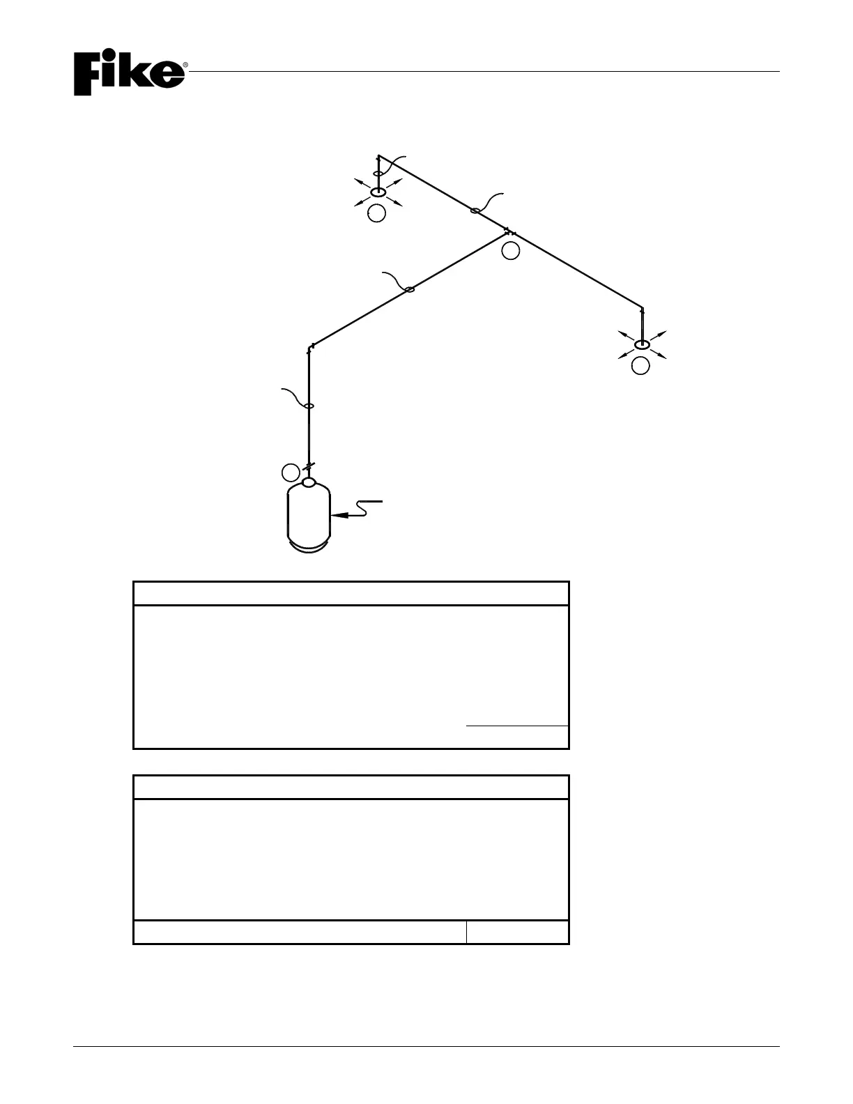
EXAMPLE: TWO NOZZLE CONFIGURATION
EXAMPLE (ENGLISH)
Section A - B 39.0’ x 0.77 (2-1/2” NPT) = 30.03 (Length Factor)
1 x 5.08 (2-1/2” x 90
o
Elbow) = 5.08 (90
o
Elbow Factor)
1 x 10.32 (2-1/2” NPT Tee) = 10.32 (Tee Factor)
Section B – C 9.67’ x 0.80 (2” NPT) = 7.74 (Length Factor)
1 x 4.40 (2” x 90
o
Elbow) = 4.40 (90
o
Elbow Factor)
TPD = 57.57
EXAMPLE (METRIC)
Section A - B 11.88 m x 2.53 (65 mm) = 30.06 (Length Factor)
1 x 5.08 (65 mm x 90
o
Elbow) = 5.08 (90
o
Elbow Factor)
1 x 10.32 (65 mm Tee) = 10.32 (Tee Factor)
Section B – C 2.95 m x 2.62 (50 mm) = 7.73 (Length Factor)
1 x 4.40 (50 mm x 90
o
Elbow) = 4.40 (90
o
Elbow Factor)
TPD = 57.59
NOTE: TPD MUST be <100> or less.
A
C
C
B
2-1/2" x 5'-0"
(65mm x 1.52m)
2-1/2" x 34'-0"
(65mm x 10.36m)
2" x 9'-0"
(50mm x 2.74m)
2" x 0'-8"
(50mm x .21m)
375 LB (170kg)