SECTION 3 – SAMPLE PROBLEM
Page 6 of 17 Fike Clean Agent System w/ FM-200™ UL / ULC Ex4623
Revision Date: January, 2010 Manual P/N: 06-215 (Rev G) FM 3010715
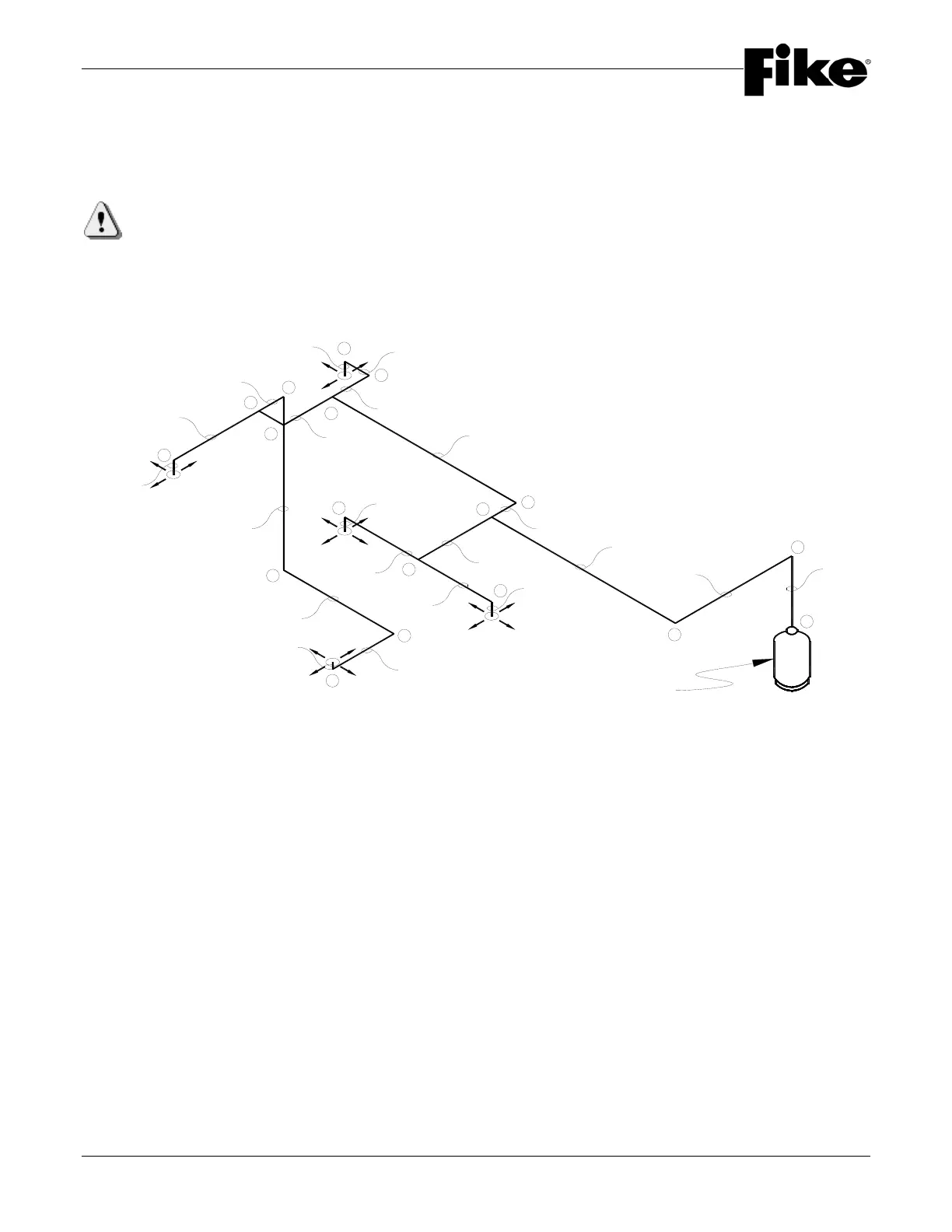
Step 2: Layout a piping isometric to show all elevation changes, fittings, pipe sizes and lengths. Pipe
sizes will be based on the flow rate for each section and selected from Table 2.6.3. Check the piping
network for tee split ratios, tee orientation, minimum piping distances, proper nozzle screen quantity and
location, etc.
IMPORTANT: Your final design “must” be checked by using Fike's HFC-227ea Engineered System Flow
Calculation Program before installation starts. When using the “Isometric” input portion of the flow
calculation program, it is not necessary to assign “Node” points to the piping isometric as the isometric
input will automatically assign node point numbers as you draw the piping system.
1
2
3
4
10
5
6
8
11
21
22
12
16
13
14
17
18
19
E1-N1
E1-N2
E2-N1
E3-N1
E4-N1
5' (1.5m)
15' (4.6m)
2.0' (0.6m)
1' (0.3m)
6' (1.8m)
1.0' (0.3m)
6' (1.8m)
6' (1.8m)
15' (4.6m)
3' (0.9m)
4' (1.3m)
2' (0.6m)
1' (0.3m)
2' (0.6m)
7' (2.1m)
1' (0.3m)
12'-3" (3.7m)
9' (2.7m)
5' (1.5m)
0.5' (0.2m)
650 lb. Container
9'-6" (2.9m)
FIGURE 3.4-C
The following pages are a copy of the Fike's HFC-227ea Engineered System Flow Calculation Program printout
showing the inputs and outputs of the program.