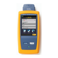
DSX-600 CableAnalyzer
Technical Reference Handbook
74
The measured value.
The limit specified by the selected test limit.
MARGIN is the difference between the measured value and the
limit. The value is negative and is in a red box if the
measurement exceeds the limit.
To switch between results for the main unit and the remote,
tap REMOTE or MAIN.
To see the results for a different pair or pairs, tap a tab.
The result for the pair. If the result shows an asterisk, see “PASS*/
FAIL* Results” on page 58.
Insertion Loss
Insertion loss is the loss of signal strength over the cabling, as
shown in Figure 30. Insertion loss is caused by the DC resistance of
the copper wire and connecting hardware, the impedance of the
twisted pairs, and by leakage of electrical energy through the
cable’s insulation. Lower values of insertion loss mean better
cabling performance.
At higher frequencies, signals tend to travel only near the surface
of a conductor. This “skin effect”, along with the cabling’s
inductance and capacitance, cause insertion loss to increase with
frequency.
Figure 31 shows the insertion loss plot. If the insertion loss test
passed, the tester puts the cursor at the worst value. If the test
failed, the cursor is at the worst margin.
 Loading...


