FIGURES
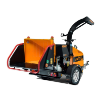
Figure 1 - Exterior components, right-hand side view 19
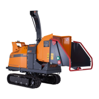
Figure 2 - Exterior components, left-hand side view 20
Figure 3 - Engine left-hand side 21
Figure 4 - Engine right-hand side 22
Figure 5 - Chipping chamber 23
Figure 6 - Feed roller controls 25
Figure 7 - Control panel 26
Figure 8 - Emergency stop button 27
Figure 9 - Information screen 28
Figure 10 - Switch status screen 28
Figure 11 - No-stress settings screen 29
Figure 12 - PIN entry screen 29
Figure 13 - Ignition switch 30
Figure 14 - Manufacturer's statutory plate 31
Figure 15 - Vehicle identification number 32
Figure 16 - Test results 41
Figure 17 - Breakaway cable 46
Figure 18 - Breakaway cable guide 46
Figure 19 - Tow hitch handle 47
Figure 20 - Tow hitch wear indicator 48
Figure 21 - Tow position 49
Figure 22 - Lifting eye 51
Figure 23 - Chute front rotation clamp 52
Figure 24 - Remove clamp and nut 53
Figure 25 - Chute rear rotation clamp 53
Figure 26 - Remove chute 54
Figure 27 - Positioning the machine 59
Figure 28 - Hopper tray locking latch 60
Figure 29 - Hopper tray locked down 60
Figure 30 - Maximum throttle position 61
Figure 31 - Key in the ON position 61
Figure 32 - Key in the engine crank position 62
Figure 33 - Throttle in idle position 62
Figure 34 - Feed roller controls 64
Redwood Global Ltd - ST6P
Operator and Maintenance Manual
7 12-00-001 v4.0