17
Fronius IG
Plus
Construction
The power stage set and the con-
nection area are separated from
each other for delivery.
Safety
WARNING! An electrical shock can be fatal. Danger from grid
voltage and DC voltage from solar modules.
- The connection area should only be opened by a licensed
electrician.
- The separate power stage set area should only be discon-
nected from the connection area after first being discon-
nected from the grid power.
- The separate power stage set area should only be opened
by Fronius-trained service personnel.
Never work with live wires! Prior to all connection work, make
sure that the AC and DC wires are not charged.
Fronius IG Plus Installation and Connection
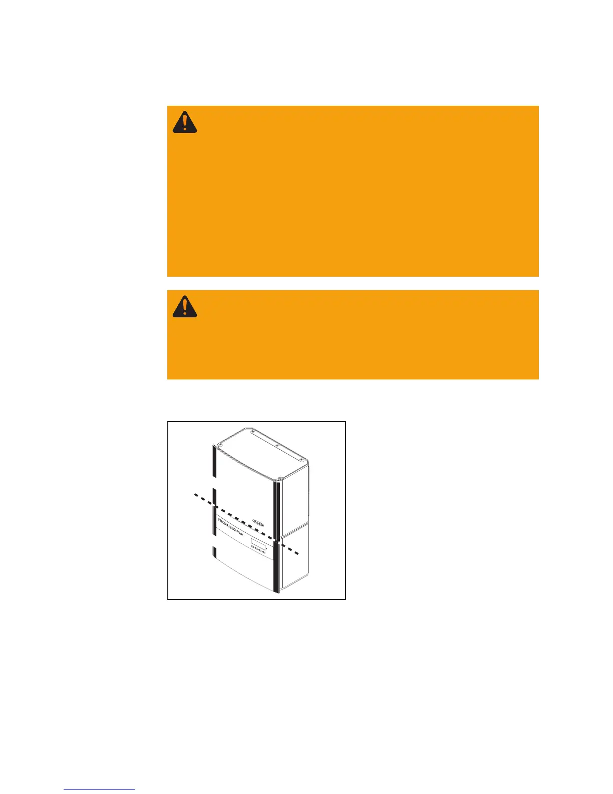
Connection area
Power stage set(s)
Connection area and power stage set on
the Fronius IG Plus
WARNING! Incorrect operation and work performed incorrectly
can cause serious injury & damage! Only qualified staff are
authorized to install your Fronius IG Plus and only within the
scope of the respective technical regulations. Do not start
operation or carry out maintenance work before you have read
the chapter ‘Safety Instructions’!