63
Selecting the
Public grid
(continued)
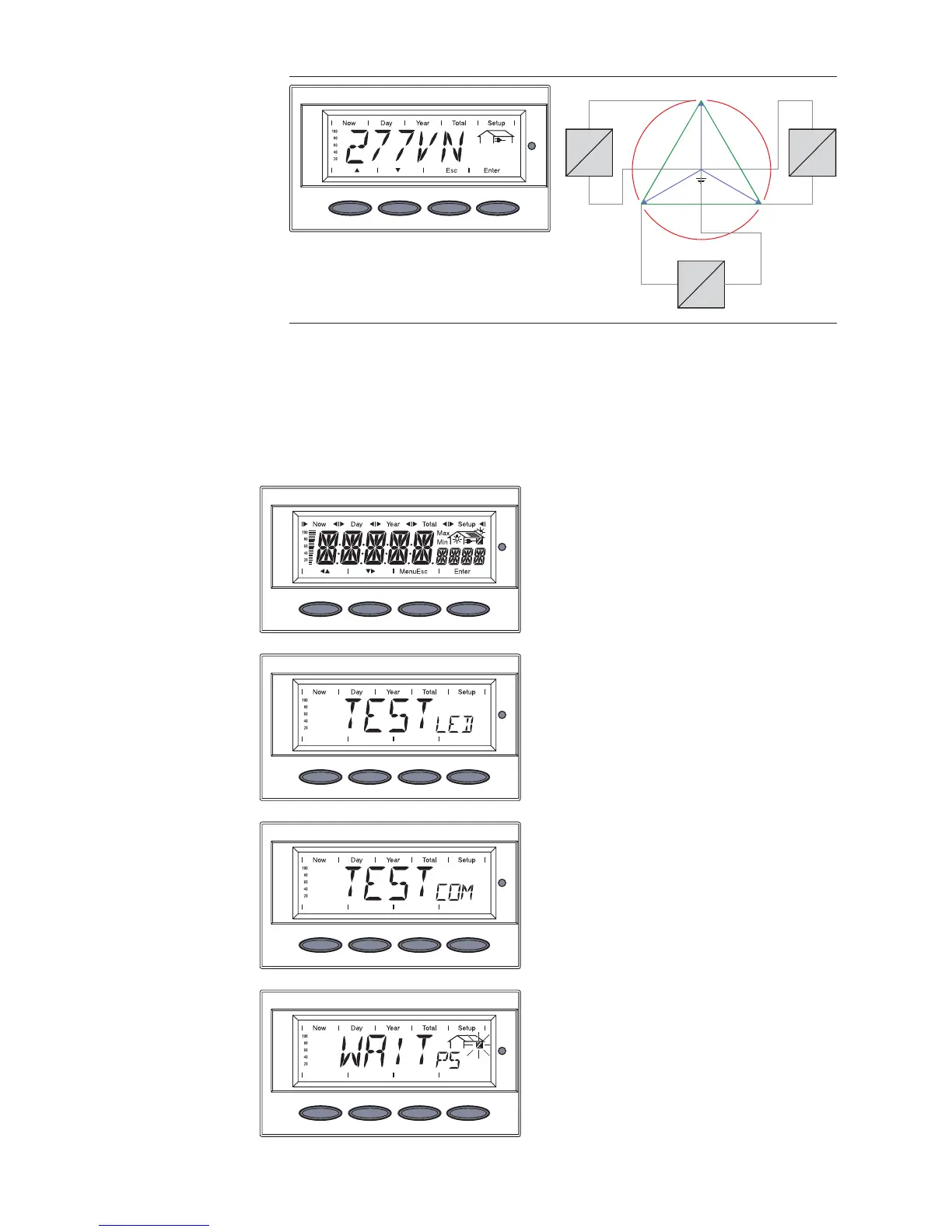
277 V
277 V
277 V
120 °
12 0 °
120 °
480 V
480V
480 V
L1
L2
N
L3
=
~
=
~
=
~
Grid voltage 480 V Delta: 277 V WYE
Neutral conductor available in the system
Neutral conductor monitoring is activated
2. Press the 'Enter' key 2x to confirm your grid selection (or use the 'Esc'
key to return to grid selection)
The startup phase starts again with the segment test.
Startup Phase
at Startup
Operation
- ‘TESTCOM’ is shown
- Synchronization with grid
‘WAITPS’ is shown: The Fronius
IG Plus is waiting for all power
supplies in the network to be on
stand-by. This procedure takes
place dependent on the DC-
voltage.
- Segment test
All display elements light up for
about one second
- The Fronius IG Plus unit goes
through a master check list for
several seconds
The display shows ‘TEST’ and
indicates the respective compo-
nent which is being tested (for
example ‘LED’)