75
Item Function
(7) area for unit display
for displaying the applicable measuring unit
(8) Icon for the ‘Enter’ key
(9) Icons for the ‘Menu/Esc’ key
(10) Icons for the ‘Down/Right’ key
(11) Icons for the ‘Left/Up’ key
(12) Area for data
for displaying the data value measured
(13) output bar (not active during setup)
indicates the power output fed into the grid at a given moment -
independent from the display mode chosen. The screen displays
% of the maximum possible output power of your solar inverter
Startup phase After switching on automatically, the Fronius IG Plus unit goes through a
self-test, followed by an extensive test of the grid. This test takes five
minutes. During the startup sequence the illumination of the Operating
Status LED is yellow.
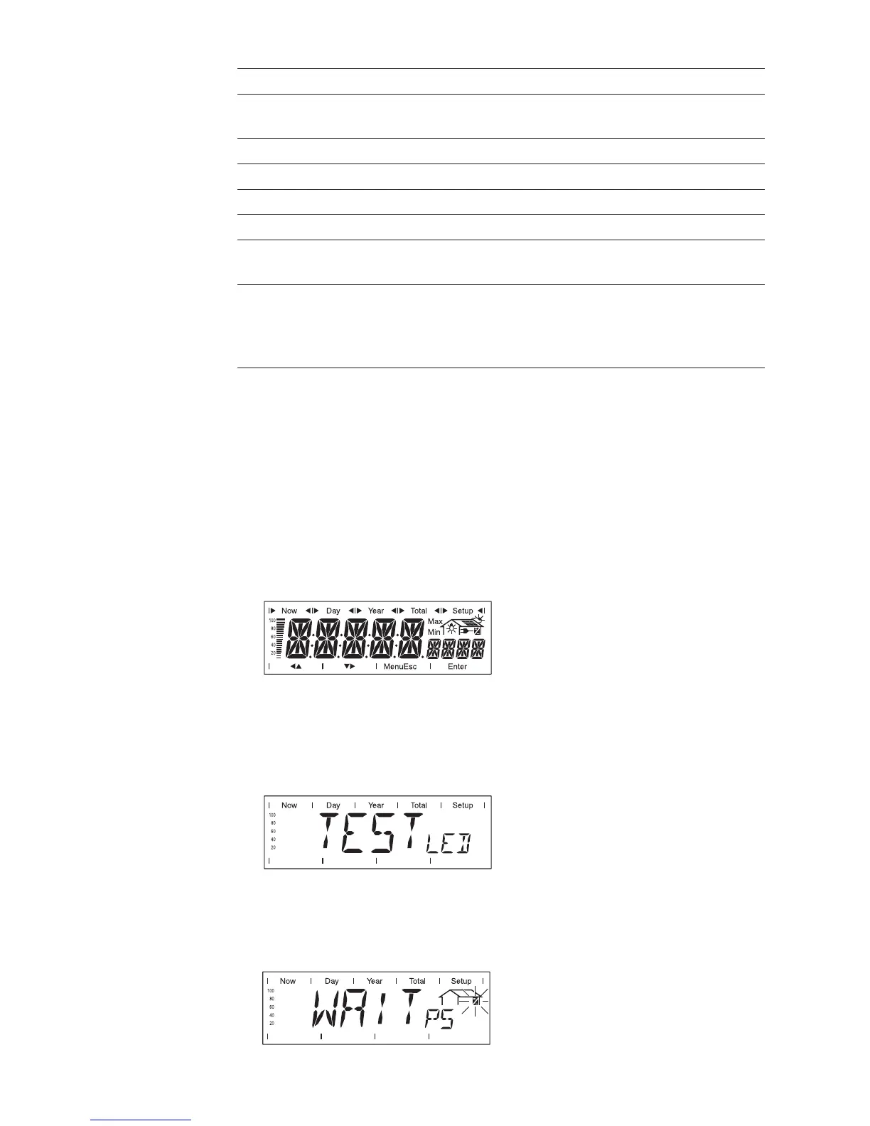
1. Segment test
All display elements light up for about one second
2. Self test of important components of the Fronius IG Plus unit
- The Fronius IG Plus unit goes through a master check list for
several seconds
- The display shows ‘TEST’ and indicates the respective component
which is being tested (for example ‘LED’)
3. Synchronization with grid
- ‘WAITPS’ is shown: The Fronius IG Plus is waiting for all power
stage sets in the network to be on stand-by. This procedure takes
place dependent on the DC-voltage.
Test Procedu-
re
Display
(continued)