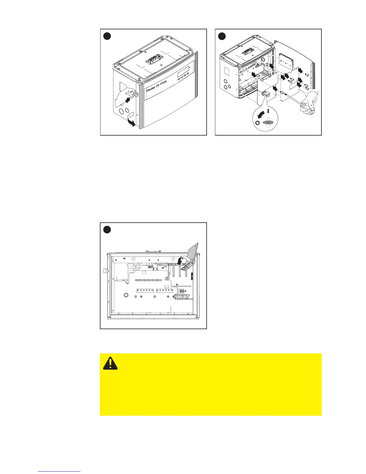
EasyManuals Logo

Fronius IG Plus 3.0-1 User Manual

Fronius IG Plus 3.0-1
175 pages
To Next Page IconTo Next Page
To Previous Page IconTo Previous Page
Page #76 background imageLoading...
Page #76 background image
66
Opening Fro-
nius IG Plus
(continued)
Inserting
Option Cards
Insert option cards into free slots.
1
2
1
2
2
3
4
5
7
6
8
9
1
Important The plastic dividers are used to separate the data communi-
cation wires from the AC and DC wires:
- Data communication wires must be laid above the plastic dividers
- AC and DC wires are laid under the plastic dividers
Make sure that the plastic dividers are present.
1
1
Connecting
Option Cards,
Laying Data
Communicati-
on Wires
CAUTION! Danger of short circuit by loose metal parts from
knockouts. Loose metal parts in the inverter may cause short
circuits when the inverter is powered up. When
removing knockouts, make sure that
- no loose metal parts fall into the inverter
- any metal pieces that do fall into the inverter are removed
immediately

Table of Contents

Questions and Answers:

Question and Answer IconNeed help?

Do you have a question about the Fronius IG Plus 3.0-1 and is the answer not in the manual?

Fronius IG Plus 3.0-1 Specifications

General IconGeneral
Protection classIP 44
Max. output current13 A
Nominal AC voltage230 V
THD< 3%
Max. DC voltage500 V
Maximum Input Voltage500 V
Number of MPP Trackers1
Operating Temperature Range-20°C to +55°C
CoolingConvection
Warranty5 years
AC nominal output3000 W
Max. apparent AC power3000 VA
AC voltage range180 - 264 V

Related product manuals