28
Fronius IG
Plus Installati-
on
(continued)
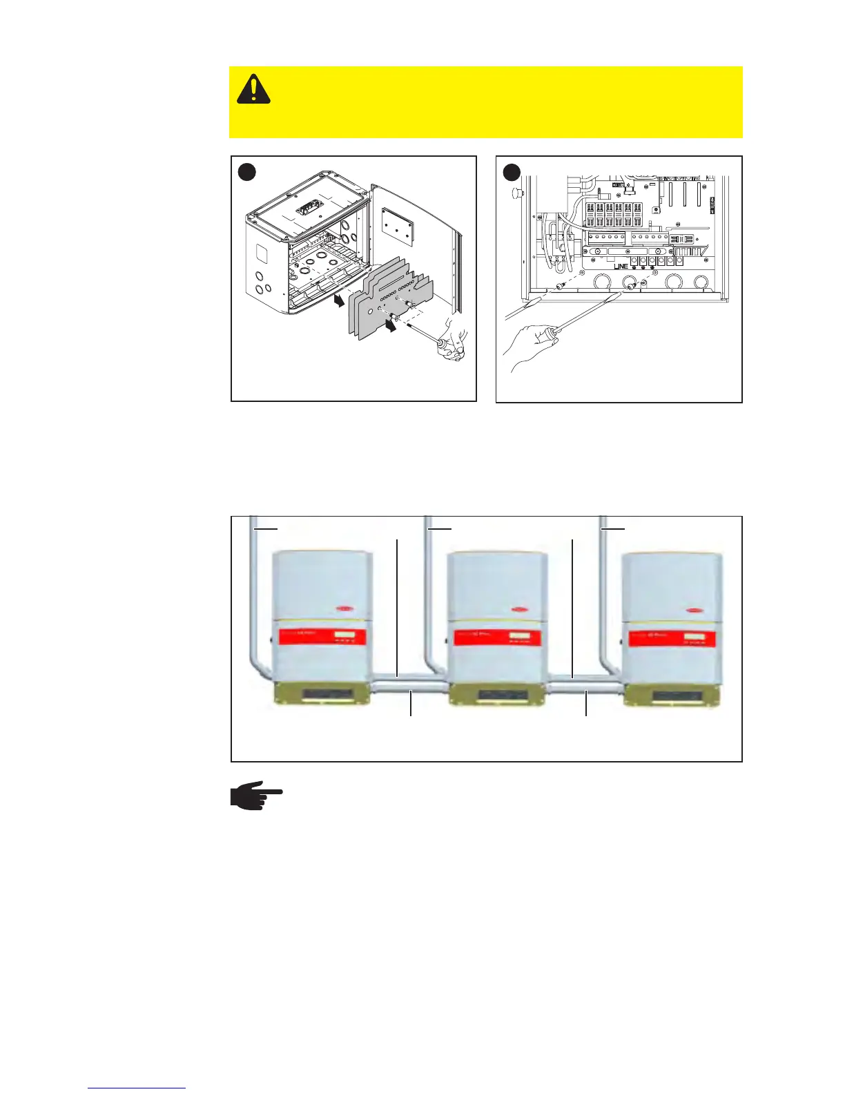
Installation of
Several Inver-
ters
Several inverters can be easily installed and connected next to each other
using the side knockouts on the Fronius IG Plus, e.g.:
DC DC DC
DATCOM = data communication
NOTE All electrical installations must be made in accordance
with the National Electrical Code, ANSI/NFPA 70, and any other
codes and regulations applicable to the installation site.
For installations in Canada the installations must be done in
accordance with applicable Canadian standards.
DATCOM DATCOM
AC AC
CAUTION! Danger of injury by falling equipment.
Attach the connection area of the inverter to the wall bracket
using the 2 screws removed from the wall bracket in step 1.
5
2
1
6