49
3
1
3
5
2
4
LOAD
LINE
4
1
3
2
4
3
1
LOAD
LINE
+
-
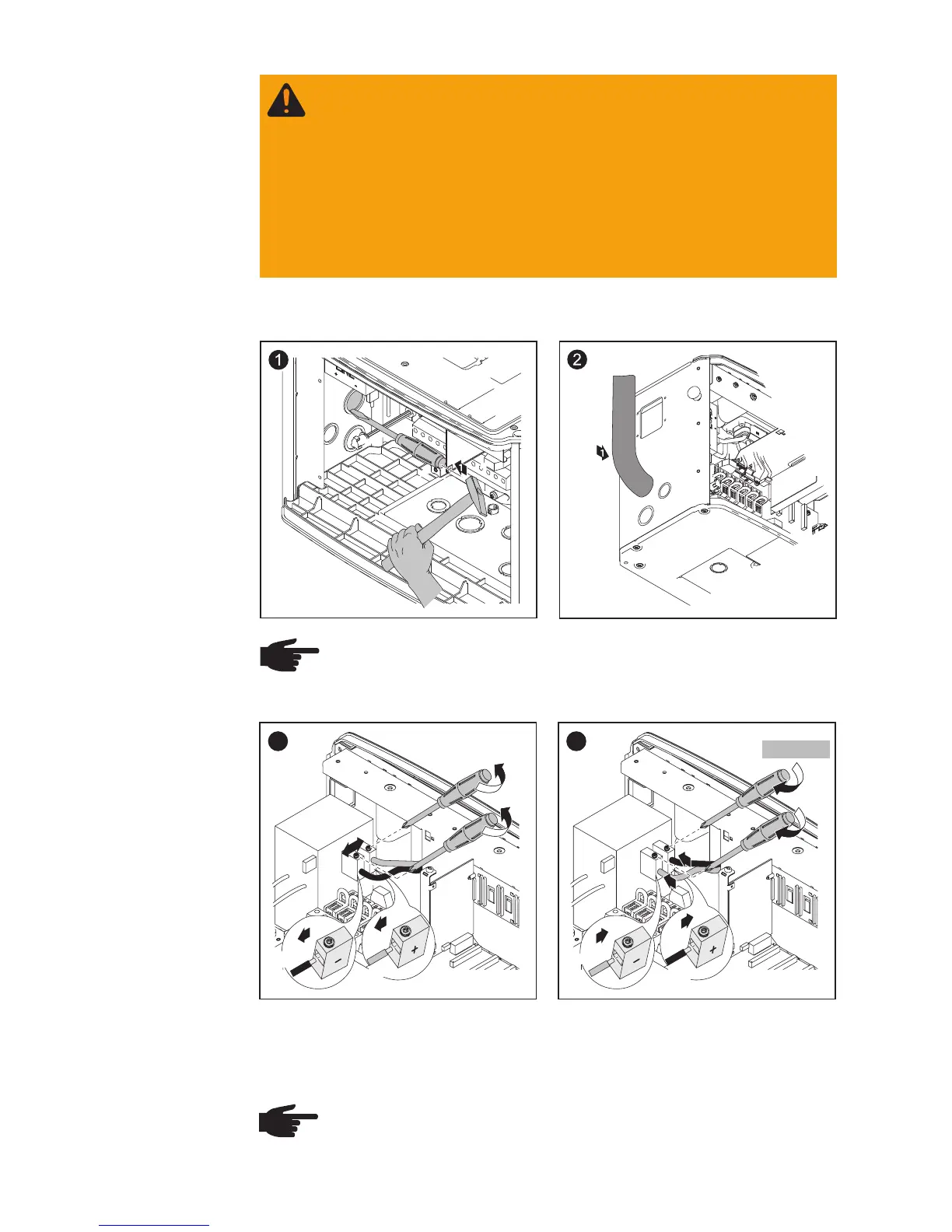
After disconnecting the DC filter wire:
- Connect the red DC+ wire to the DC- filter terminal as per step 4
- Connect the black DC- wire to the DC+ filter terminal as per step 4
NOTE Identify the reversed polarity accordingly with (+) and (-)
at the DC input terminal blocks.
Solar Module
Ground at
Positive Pole:
Connecting
Solar Module
Strings
Wire Cross
Section of
Solar Module
Strings
(continued)
WARNING! An electric shock can be fatal. Inadequately sized
electrical components can cause serious injuries to persons
and damage to (or loss of) property.
- Use minimum AWG 14 to maximum AWG 6, min. 167°F
(75°C), copper wire for all DC wiring connections to the
Fronius IG Plus. Voltage drop and other considerations may
dictate larger size wires be used.
- Use only solid or stranded wire. Do not use fine stranded
wire.
NOTE Only use water tight conduit fittings and conduits.
Conduit fittings and conduits are not part of the scope of delivery
for the inverter.
Conduit
black
red
red
black
1.33 ft. lb.