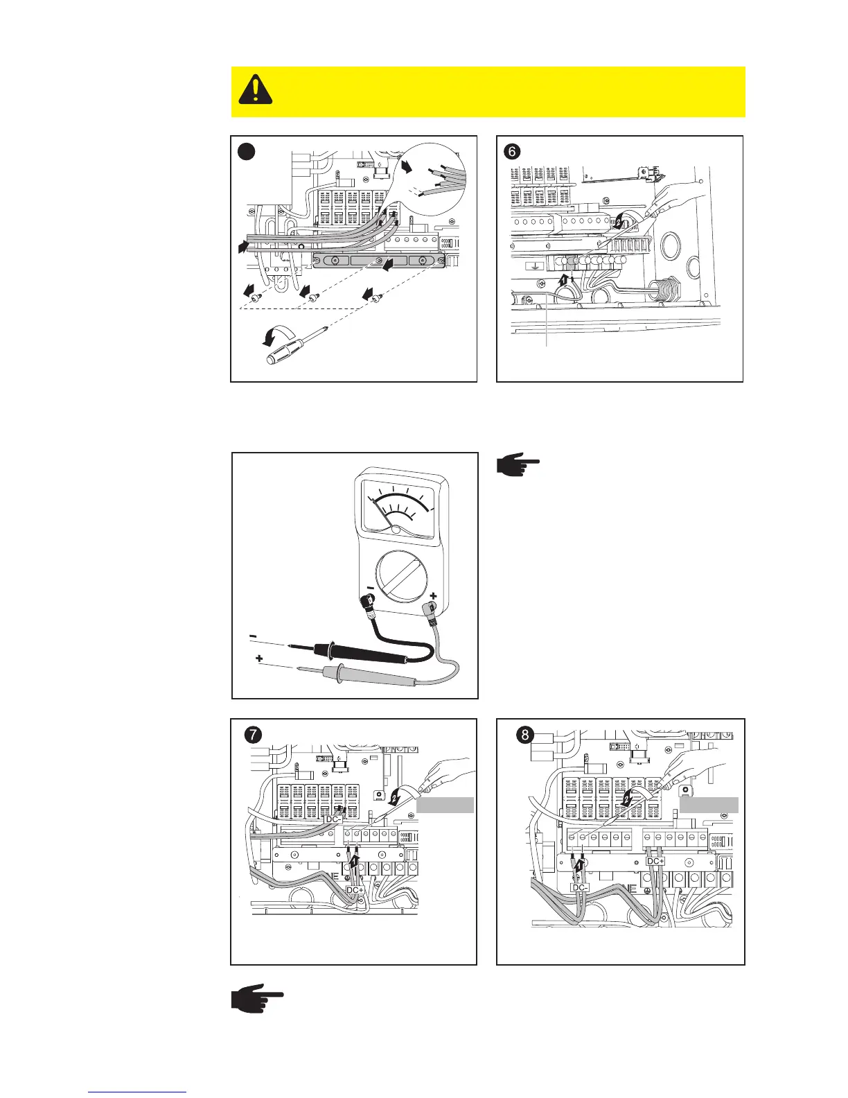
EasyManuals Logo

Fronius IG Plus 3.0-1 User Manual

Fronius IG Plus 3.0-1
175 pages
To Next Page IconTo Next Page
To Previous Page IconTo Previous Page
Page #60 background imageLoading...
Page #60 background image
50
Solar Module
Ground at
Positive Pole:
Connecting
Solar Module
Strings
(continued)
1
3
5
1/2 in.
2
4
5
4
6
*
Wire for solar module grounding
NOTE Connecting the
DC wiring with the wrong
polarity may cause dama-
ge to the inverter.
Check both the polarity and the
open circuit voltage.
The DC Voltage must not exceed
600 V, regardless of temperature.
NOTE
Form a min. 4 in. wire loop using all wires.
Tightening torque:
stranded wires ................1.25 ft. lb.
solid wires ......................0.81 ft. lb.
1.33 ft. lb.
1.33 ft. lb.
Tightening torque for solid and stranded
wires
Tightening torque for solid and stranded
wires
CAUTION! Danger of damaging the inverter by overload.
Connect a maximum of 20 A to one single DC input terminal.

Table of Contents

Questions and Answers:

Question and Answer IconNeed help?

Do you have a question about the Fronius IG Plus 3.0-1 and is the answer not in the manual?

Fronius IG Plus 3.0-1 Specifications

General IconGeneral
Protection classIP 44
Max. output current13 A
Nominal AC voltage230 V
THD< 3%
Max. DC voltage500 V
Maximum Input Voltage500 V
Number of MPP Trackers1
Operating Temperature Range-20°C to +55°C
CoolingConvection
Warranty5 years
AC nominal output3000 W
Max. apparent AC power3000 VA
AC voltage range180 - 264 V

Related product manuals