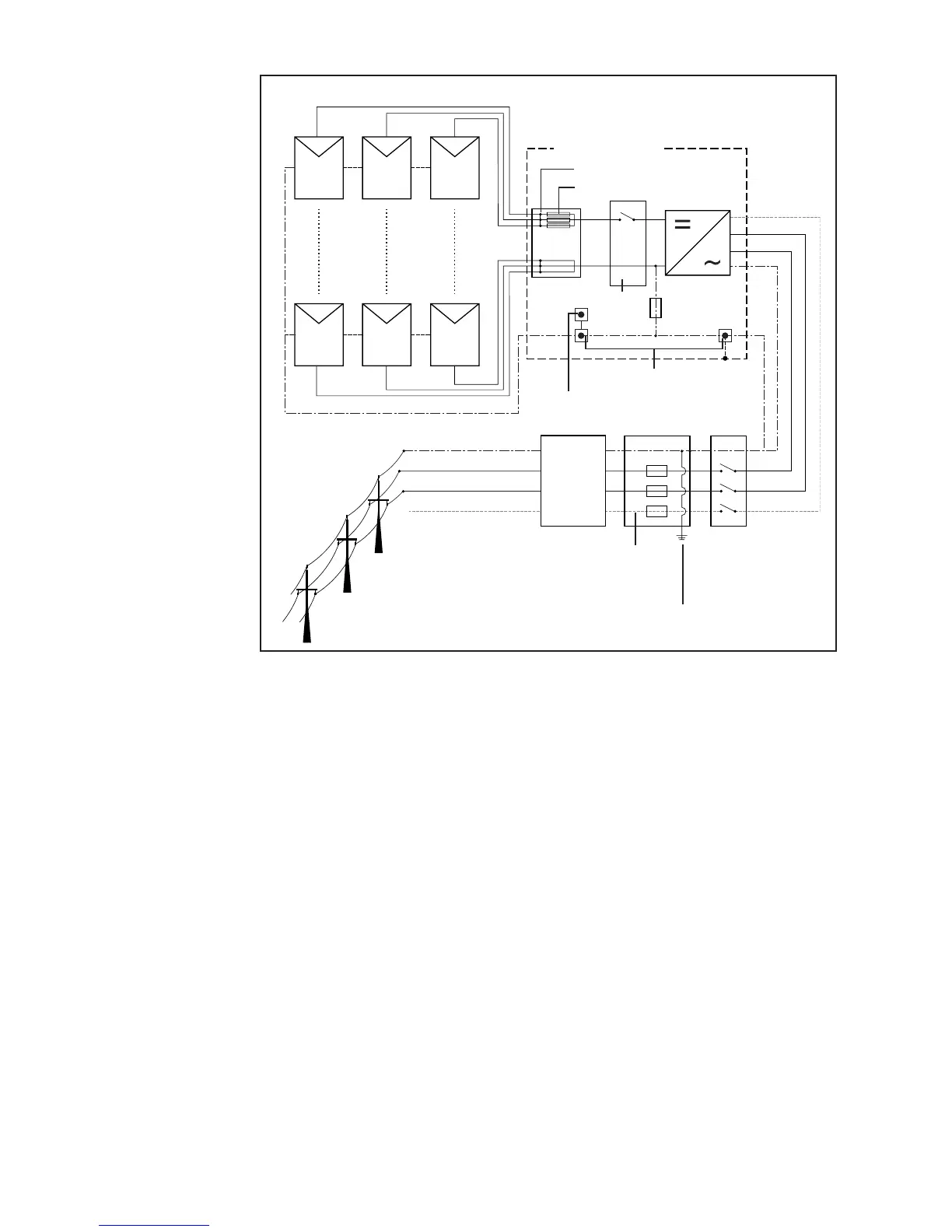
EasyManuals Logo

Fronius IG Plus 3.0-1 User Manual

Fronius IG Plus 3.0-1
175 pages
To Next Page IconTo Next Page
To Previous Page IconTo Previous Page
Page #28 background imageLoading...
Page #28 background image
18
Fronius IG Plus
Connection
Diagramm
Energy-
meter
AC distribution
panel
DC disconnect
DC terminal block
String fuses
DC +
DC -
PV frame ground
L1
L2
N
Grounding terminal
Grounding electrode terminal *
L1
N**
L2
L3
L3***
Main grounding system
* may be required by local authorities
** may be required depending on grid configuration
*** depending on inverter type
Lockable AC
disconnect
switch
Overview ‘Fronius IG Plus Installation and Connection’ contains the following sec-
tions:
- Fronius IG Plus Connection Options
- Knockouts on the Fronius IG Plus
- Choosing the Location
- Fronius IG Plus Installation
- Connecting the Fronius IG Plus to the Public Grid (AC)
- Connecting Solar Module Strings to the Fronius IG Plus (DC)
- Attaching Power Stage Sets and Closing the Fronius IG Plus

Table of Contents

Questions and Answers:

Question and Answer IconNeed help?

Do you have a question about the Fronius IG Plus 3.0-1 and is the answer not in the manual?

Fronius IG Plus 3.0-1 Specifications

General IconGeneral
Protection classIP 44
Max. output current13 A
Nominal AC voltage230 V
THD< 3%
Max. DC voltage500 V
Maximum Input Voltage500 V
Number of MPP Trackers1
Operating Temperature Range-20°C to +55°C
CoolingConvection
Warranty5 years
AC nominal output3000 W
Max. apparent AC power3000 VA
AC voltage range180 - 264 V

Related product manuals