31
NOTE For optimal functioning of grid monitoring the resistance
in the leads to the AC side connection terminals must be as low
as possible.
The AC conductor resistance between the Fronius IG Plus unit
and the building’s distribution panel should not exceed 0.5 Ohm.
Monitoring the
Grid
For larger photovoltaic schemes it is possible to connect several Fronius
IG Plus units in parallel without any problems.
To ensure symmetrical feeding, connect the inverters uniformly to all
phases.
NOTE The Fronius IG Plus is designed to be connected to
three phase systems. Utilities generally allow up to 6 kVA of
unbalance but check with your utility and try to balance the instal-
lation. The connection to the grid shall be done in the following
way:
208 V / 240 V:
- Connect Fronius IG Plus No. 1, No. 4, No. 7, ... to L1 and L2
- Connect Fronius IG Plus No. 2, No. 5, No. 8, ... to L2 and L3
- Connect Fronius IG Plus No. 3, No. 6, No. 9, ... to L1 and L3
277 V:
- Connect Fronius IG Plus No. 1, No. 4, No. 7, ... to L1 and N
- Connect Fronius IG Plus No. 2, No. 5, No. 8, ... to L2 and N
- Connect Fronius IG Plus No. 3, No. 6, No. 9, ... to L3 and N
Schemes with
more than one
inverter
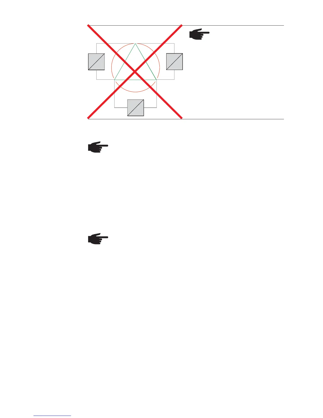
NOTE Do not connect
Fronius IG Plus inverters
to the 480 V Delta power
grid.
480 V
480 V
480 V
120 °
120 °
12 0 °
L1
L2L3
=
~
=
~
=
~
480 V Delta
Overview of
Available
Power Grids
(continued)