69
Solar Net and
Data Interface
(continued)
In order to uniquely define each Fronius IG Plus in Solar Net,
each Fronius IG Plus must also be assigned an individual number.
You can assign individual numbers as per ‘The Setup Menu’ section in
this manual.
More detailed information on the individual system upgrades can be found
in the relevant operating instructions or on the Internet at
http://www.fronius-usa.com.
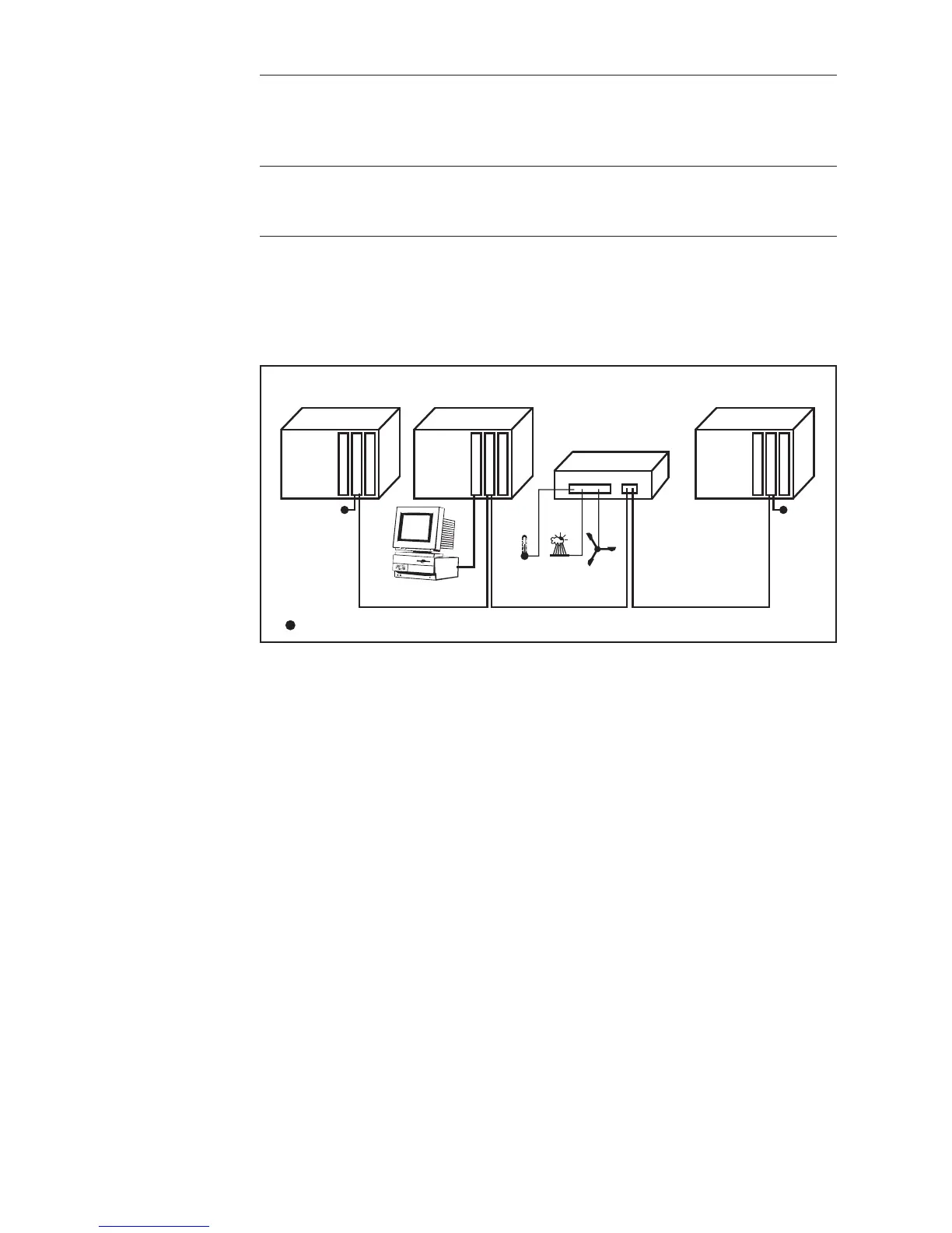
Example
12 3
Fronius
IG Plus
Fronius
IG Plus
Fronius
IG Plus
Com Card
Datalogger C.
IN OUT
Com Card
Com Card
IN OUT
RS 232
IN
OUT
Sensor Box
IN OUT
°C
W/m²
m/s
PC
Logging and archiving data from the inverter and sensor using a Datalog-
ger and sensor box.
Data network with 3 Fronius IG Plus units and one sensor box:
- all Fronius IG Plus units have one ‘Fronius Com Card’
- one Fronius IG Plus has a ‘Datalogger card’ (no. 2)
- Datalogger has two RS-232 interfaces for connecting to a PC and a modem
Termination plug
Option cards communicate within the Fronius IG Plus via its internal net-
work. External communication (Solar Net) takes place via the ‘Fronius
Com Cards.’ Each ‘Fronius Com Card’ is equipped with two RS485 inter-
faces - an input and an output. RJ45 plug connectors are used to connect
to these cards.