35
Recommenda-
tion for the
AC-side over
current pro-
tection
NOTE To reduce the risk of fire, connect only to a circuit provi-
ded with branch circuit overcurrent protection in accordance with
the National Electrical Code, ANSI / NFPA 70, at a MAXIMUM of:
Fronius IG Plus Over Current Protection
208 V 240 V 277 V
3.0-1 20 A 20 A 15 A
3.8-1 25 A 20 A 20 A
5.0-1 30 A 30 A 25 A
6.0-1 40 A 35 A 30 A
7.5-1 45 A 40 A 35 A
10.0-1 60 A 60 A 45 A
11.4-1 70 A 60 A 60 A
11.4-3 40 A 35 A -
12.0-3 - - 20 A
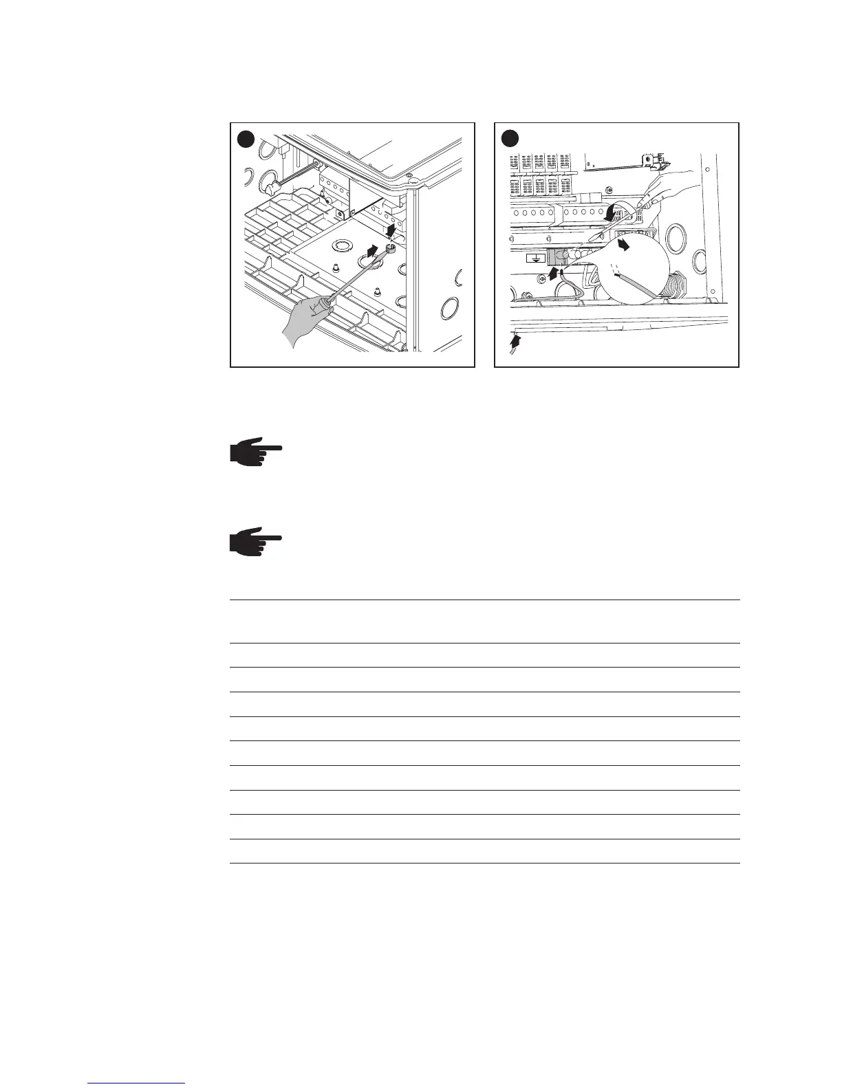
Connecting
Grounding
Electrode Wire
If the photovoltaic system requires a grounding electrode, it should be
connected as follows:
NOTE
Form a min. 4 in. wire loop with the wire.
Tightening torque:
stranded wires ................1.25 ft. lb.
solid wires ......................0.81 ft. lb.
1
1
2
2
4
3
1
1/2 in.
2
Depending on the installation, an additional external AC and/or DC dis-
connect may be required if the inverter is installed in a location not easily
accessible to utility or fire personnel. Consult local authorities for additio-
nal information.
Additional
External AC
and/or DC
Disconnect