41
Connecting
Solar Module
Strings
(continued)
9
DC+
DC-
10
3
1
2
SMON
SMOFF
Important The Fronius IG Plus is shipped with conductive slugs in the
fuseholders. Series fusing may be required depending on the type of PV
module used in the system. See NEC 690.9.
Select string fuses according to the information from the solar module
manufacturer or as per ‘Criteria for the Proper Selection of String
Fuses’ (max. 20 A per single DC input terminal)
Important
- Follow all solar module safety instructions
- Follow all solar module manufacturer requirements
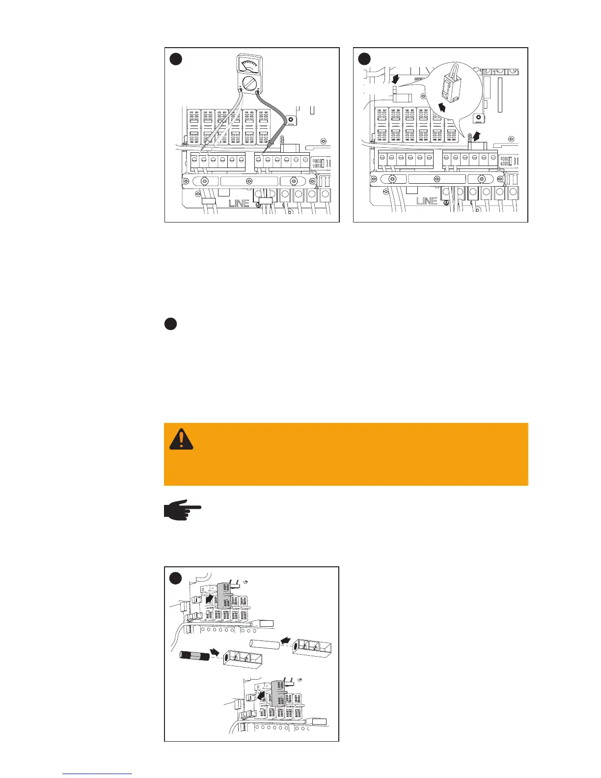
Inserting
String fuses
into the Froni-
us IG Plus
1
NOTE
- Insert fuses only with a fuse cover in the respective fuse
holder
- Do not operate the Fronius IG Plus without fuse covers
1
4
2
3
2
DC-
DC-
WARNING! An electrical shock can be fatal. Danger from DC
voltage from solar modules.
Fuse covers are for installation purposes only. They offer no
protection against contact.