40
DC+
5
2
DC-
1
DC+
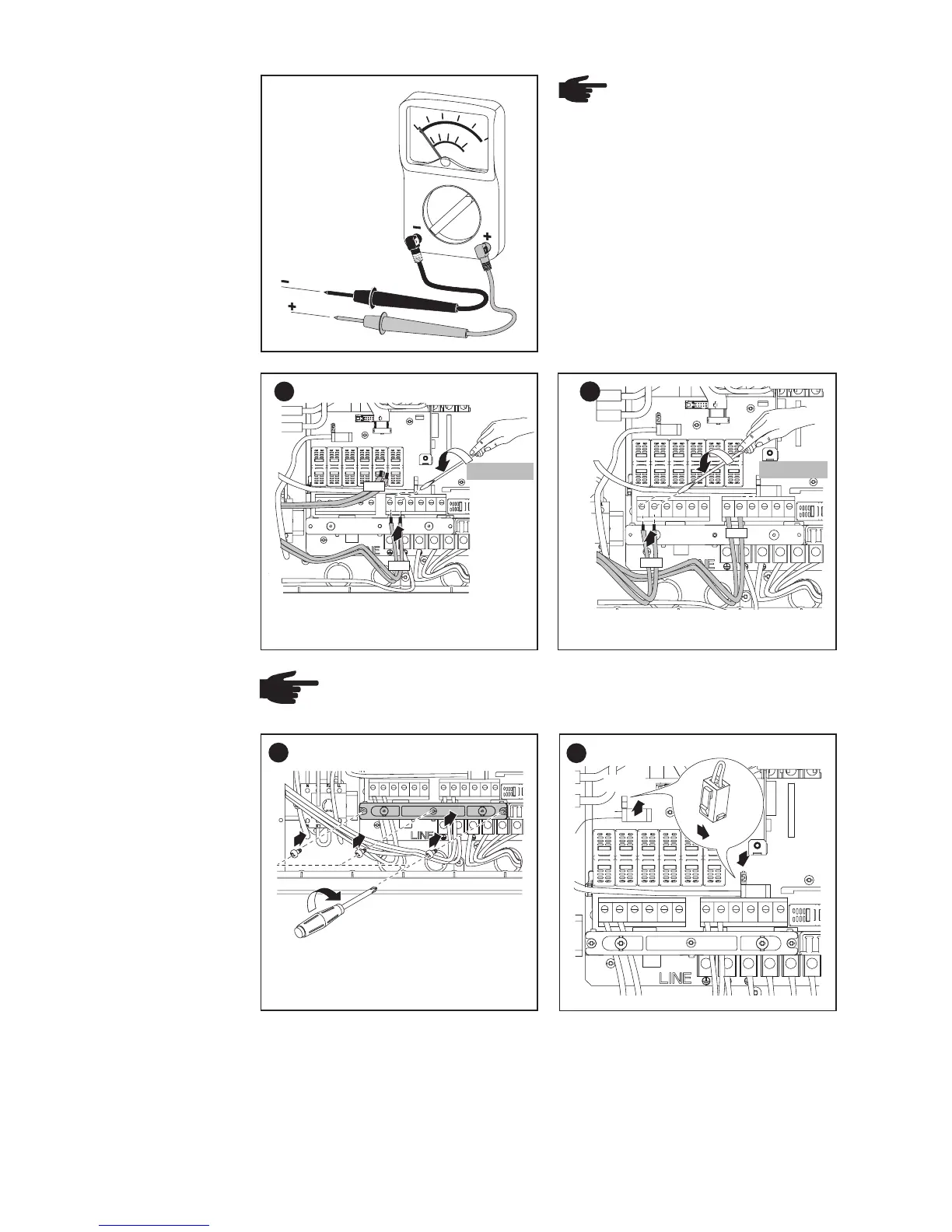
Connecting
Solar Module
Strings
(continued)
NOTE Connecting the
DC wiring with the wrong
polarity may cause dama-
ge to the inverter.
Check both the polarity
and the open circuit volta-
ge.
The DC Voltage must not exceed
600 V, regardless of temperature.
3
6
2
DC-
1
DC+
1.33 ft. lb.
NOTE
Form a min. 4 in. wire loop using all wires.
7
4
1
2
2
2
3
3
1
2
8
SMON
SMOFF
Important
- Set the jumper from the ‘SMON’ position to the ‘SMOFF’ position for
correct measurement results
- Check the polarity and voltage of the solar module strings: the DC-
voltage must not exceed 600 V, the difference between the individual
solar module strings should be less than 10 V.
1.33 ft. lb.
Tightening torque for solid and stranded
wires
Tightening torque for solid and stranded
wires