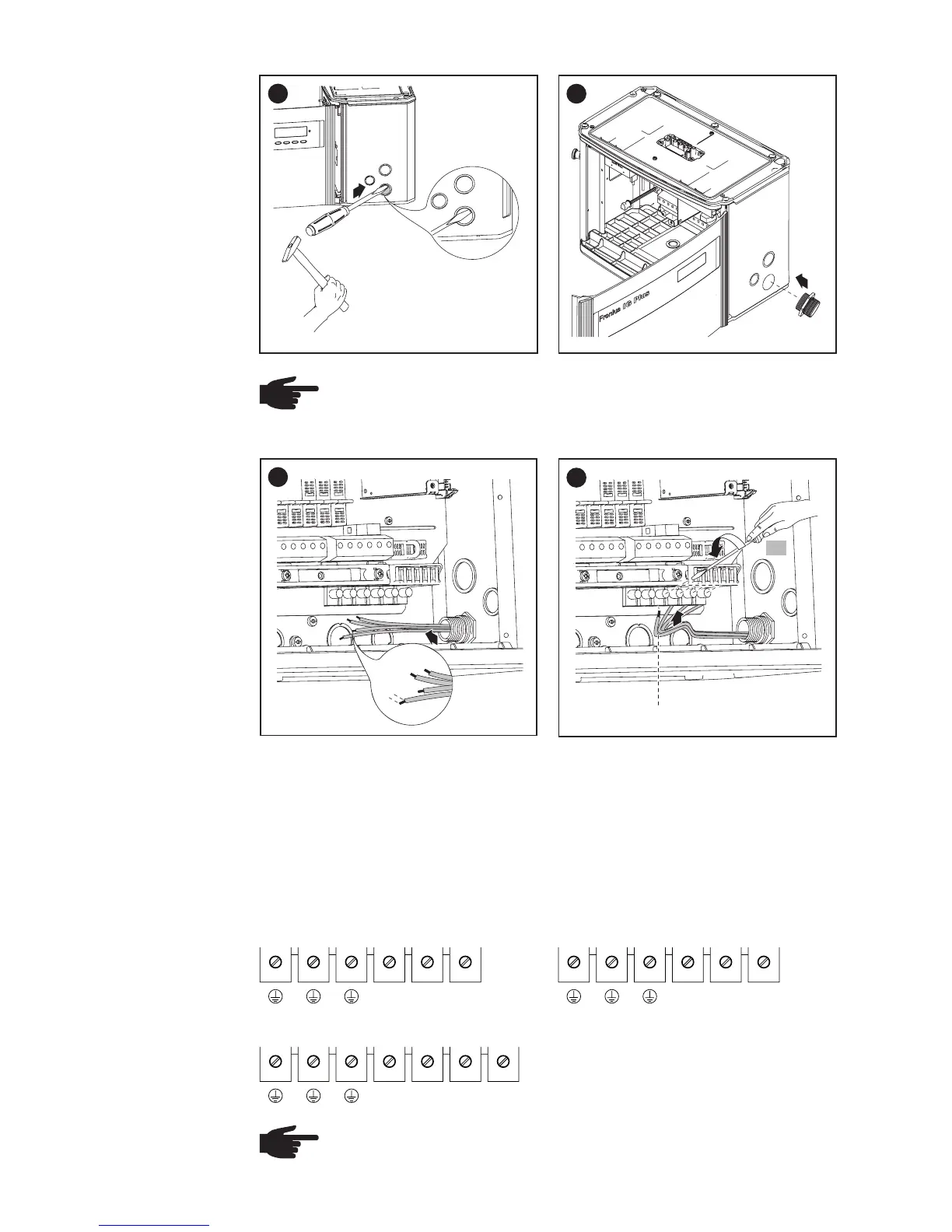
EasyManuals Logo

Fronius IG Plus 3.0-1 User Manual

Fronius IG Plus 3.0-1
175 pages
To Next Page IconTo Next Page
To Previous Page IconTo Previous Page
Page #44 background imageLoading...
Page #44 background image
34
4
2
1
Connecting
the Fronius IG
Plus to the
Public Grid
(AC)
L1 L2 N
1 phase - 277 V
GET
GET
1
1
2
Conduit
NOTE Only use water tight conduit fittings and conduits.
Conduit fittings and conduits are not part of the scope of delivery
for the inverter
1/2 in.
3
1
*
* Connect grid grounding / grounding conductor to the right terminal
** Tightening torque:
- stranded wires .............. 1.25 ft. lb.
- solid wires..................... 0.81 ft. lb.
Connect the AC wires to the AC-side terminals depending on the power
grid and phase quantity of the inverter:
L1 N N.C.
NOTE
Form a min. 4 in. wire loop using all wires.
**
1 phase - 208 V / 240 V
3 phases - 208 V / 240 V / 277 V
L1 L2 NL3
GET = Grounding Electrode Terminal
N.C. = Not connected

Table of Contents

Questions and Answers:

Question and Answer IconNeed help?

Do you have a question about the Fronius IG Plus 3.0-1 and is the answer not in the manual?

Fronius IG Plus 3.0-1 Specifications

General IconGeneral
Protection classIP 44
Max. output current13 A
Nominal AC voltage230 V
THD< 3%
Max. DC voltage500 V
Maximum Input Voltage500 V
Number of MPP Trackers1
Operating Temperature Range-20°C to +55°C
CoolingConvection
Warranty5 years
AC nominal output3000 W
Max. apparent AC power3000 VA
AC voltage range180 - 264 V

Related product manuals