EasyManuals Logo

Fronius IG Plus 3.0-1 User Manual

Fronius IG Plus 3.0-1
175 pages
To Next Page IconTo Next Page
To Previous Page IconTo Previous Page
Page #77 background imageLoading...
Page #77 background image
67
2
1
1
1
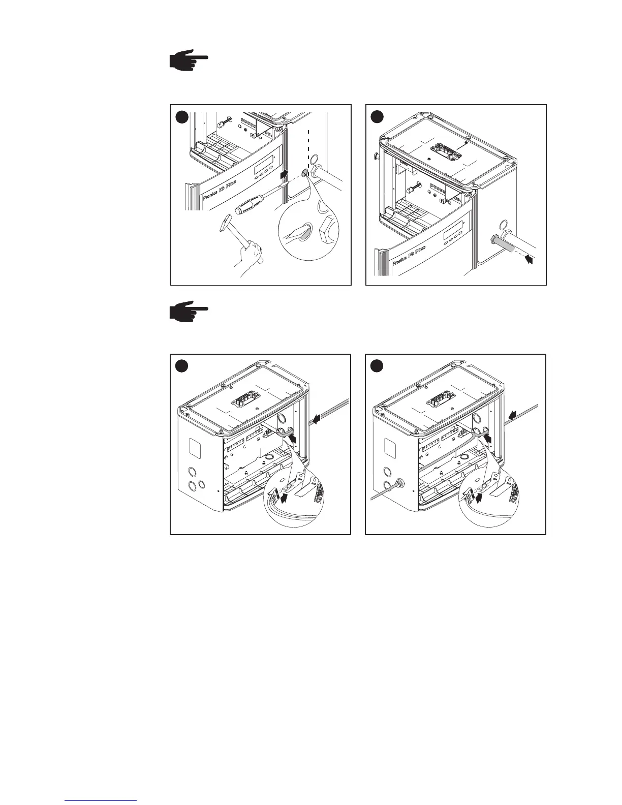
NOTE The knockout for the data communication wire must be
above the plastic dividers so that the plastic dividers are always
under the data communication wire.
* Position of
Connecting
Option Cards,
Laying Data
Communicati-
on Wires
(continued)
*
plastic dividers
NOTE Only use water tight conduit fittings and conduits.
Conduit fittings and conduits are not part of the scope of delivery
for the inverter.
Conduit
3
2
1
2
4
2
1
1
2
3 = one wire input for both data communication wires
4 = separated wire inputs on opposite sides (e.g. when several inverters
are installed next to each other)

Table of Contents

Questions and Answers:

Question and Answer IconNeed help?

Do you have a question about the Fronius IG Plus 3.0-1 and is the answer not in the manual?

Fronius IG Plus 3.0-1 Specifications

General IconGeneral
Protection classIP 44
Max. output current13 A
Nominal AC voltage230 V
THD< 3%
Max. DC voltage500 V
Maximum Input Voltage500 V
Number of MPP Trackers1
Operating Temperature Range-20°C to +55°C
CoolingConvection
Warranty5 years
AC nominal output3000 W
Max. apparent AC power3000 VA
AC voltage range180 - 264 V

Related product manuals