84
Within display
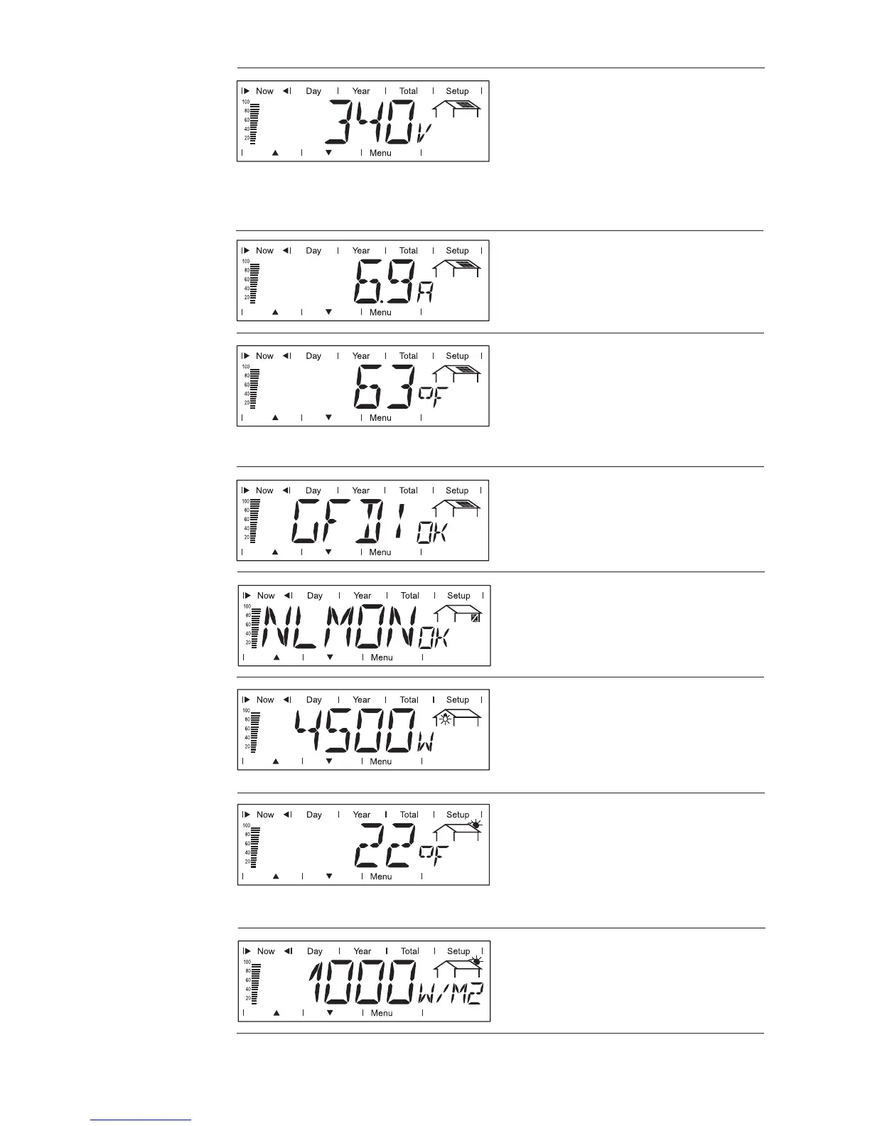
mode ‘Now’
displayed data
(continued)
DC array voltage
voltage of the solar array at the
moment of data display (Volts)
DC array current
current supplied by solar array at
the moment of data display
(Amperes)
The voltage shown while AC power is supplied is called MPP voltage
(MPP = maximum power point).
Module temperature (optional)
temperature at solar modules (°F;
can also be set for °C; this corres-
ponds to temperature sensor No.1;
Sensor Box, Datalogger and tem-
perature sensor required)
GFDI-Status
if there is no ground fault in the
system, ‘OK GFDI’ is shown
Power drawn from the grid (opti-
onal)
present consumption (Watts; Sen-
sor Box, Datalogger and load sen-
sor required)
Ambient temperature (optional)
(° F; can also be set for ° C in
setup menu; this corresponds to
temperature sensor No.2; Sensor
Box, Datalogger and temperature
sensor required)
Irradiance (optional)
the sunlight’s power per square
meter (Watts/m²; Sensor Box and
irradiance sensor required)
NL-MON Communication
When the communication with the
plug-in card ‘NL-MON’ sustains
‘NLMONOK’ is shown.