5.3 Description of Function Codes 5.3.8 J codes (Applied functions)
D differential time (J05)
J05 specifies the differential time for the PID processor.
• Data setting range: 0.00 to 600.00 (s)
0.00 indicates that the differential component is ineffective.
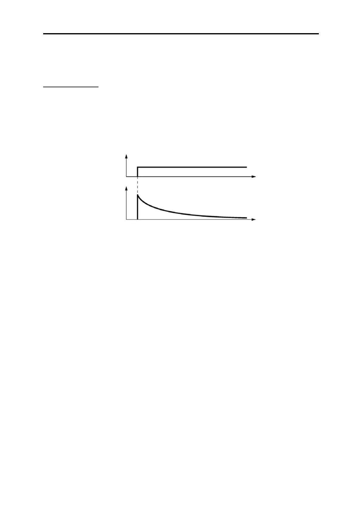
D (Differential) action
An operation in which the MV (manipulated value: output frequency) is proportional to the differential value of the
deviation is called D action, which outputs the MV that differentiates the deviation. D action makes the inverter
quickly respond to a rapid change of deviation.
The effectiveness of D action is expressed by differential time as parameter, that is J05 data. Setting a long
differential time will quickly suppress oscillation caused by P action when a deviation occurs. Too long differential
time makes the inverter output oscillation more. Setting short differential time will weakens the suppression effect
when the deviation occurs.
The combined uses of P, I, and D actions are described below.
(1) PI control
PI control, which is a combination of P and I actions, is generally used to minimize the remaining deviation caused
by P action. PI control always acts to minimize the deviation even if a commanded value changes or external
disturbance steadily occurs. However, the longer the integral time of I action, the slower the system response to
quick-changed control. P action can be used alone for loads with very large part of integral components.
(2) PD control
In PD control, the moment that a deviation occurs, the control rapidly generates greater MV (manipulated value:
output frequency) than that generated by D action alone, to suppress the deviation increase. When the deviation
becomes small, the behavior of P action becomes small. A load including the integral component in the controlled
system may oscillate due to the action of the integral component if P action alone is applied. In such a case, use
PD control to reduce the oscillation caused by P action, for keeping the system stable. That is, PD control is applied
to a system that does not contain any damping actions in its process.
(3) PID control
PID control is implemented by combining P action with the deviation suppression of I action and the oscillation
suppression of D action. PID control features minimal control deviation, high precision and high stability. In particular,
PID control is effective to a system that has a long response time to the occurrence of deviation.
Follow the procedure below to set data to PID control function codes.
It is highly recommended that you adjust the PID control value while monitoring the system response waveform of
the PID feedback with an oscilloscope or equivalent. Repeat the following procedure to determine the optimal
solution for each system.
• Increase the data of J03 (PID control P (Gain)) within the range where the feedback signal does not oscillate.
• Decrease the data of J04 (PID control I (Integral time)) within the range where the feedback signal does not
oscillate.
• Increase the data of J05 (PID control D (Differential time)) within the range where the feedback signal does not
oscillate.

 Loading...


