8.1 Meanings of Symbols Used in the Control Block Diagrams
8-1
BLOCK DIAGRAMS FOR CONTROL LOGIC
The high-performance, multi-function inverter FRENIC-MEGA is provided with various functions that allow
operations to meet the application requirements. Refer to Chapter 5 “FUNCTION CODES” for details of each
function code.
Function codes are mutually related and priority order is given depending on the function codes and data thereof.
This chapter shows major internal control block diagrams. Understand the diagrams together with the explanation
of each function code to correctly set up each function code.
Note that the internal control block diagrams show only the function codes mutually related. Refer to Chapter 5
“FUNCTION CODES” for function codes operated individually and each function code explanation.
8.1 Meanings of Symbols Used in the Control Block Diagrams
This section explains major codes, with examples, used in the block diagrams from the next item.
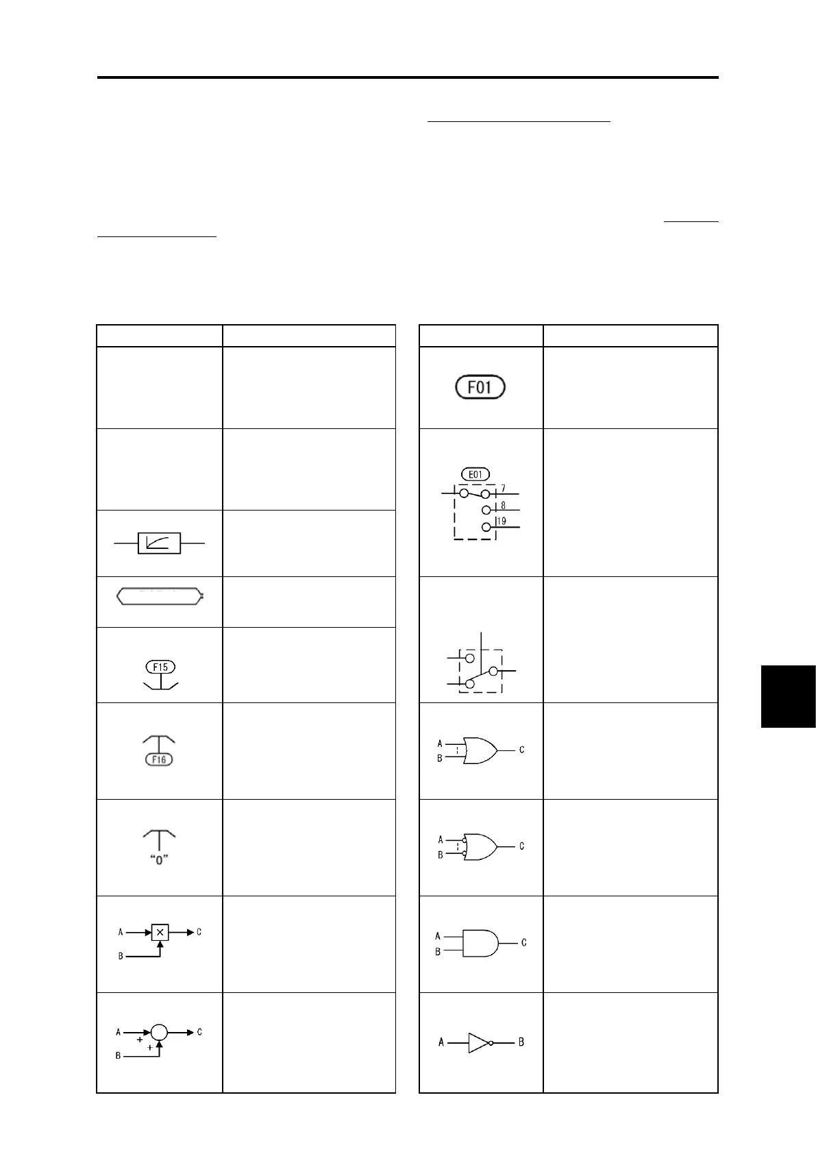
Table 8.1-1 Codes and meanings
These symbols denote
general-purpose
input/output terminals of the
inverter control circuit
terminal blocks.
This denotes a function
code.
These symbols denote
control signals (input) or
state signals (output)
allocated to the control
circuit terminals.
This indicates a switch
controlled by a function
code. Figures of switch
terminals indicate function
code data.
This is a low-pass filter.
Time constant is changeable
based on function code
data.
This symbol denotes control
command used inside the
inverter.
This indicates a switch
controlled by an internal
function control command.
The example on the left
indicates a link operation
selection command “LE”
allocated to a digital input
terminal.
This indicates upper limit
limiter. This limits an upper
limit value by function code
setting or a constant.
This indicates lower limit
limiter. This limits a lower
limit value by function code
setting or a constant.
This denotes a logical sum
(OR) circuit.
In the case of the positive
logic, when any one of inputs
is ON, C=ON, and when all
inputs are OFF, C=OFF.
This is 0 (zero) limiter. This
prevents data from
becoming minus.
This denotes an NOR
(NOR-OR) circuit.
In the case of the positive
logic, when any one of inputs
is OFF, C=ON, and when all
inputs are ON, C=OFF.
This denotes a set
frequency given by a current
or a voltage. This is a gain
analog multiplier for an
analog output signal etc.,
calculated by C = A x B.
This denotes a conjunction
(AND) circuit.
In the case of the positive
logic, only when A=ON and
B=ON, C=ON, and C=OFF
under other conditions.
This denotes an adder of
two signals or amounts,
calculated by C = A + B.
This becomes a subtracter
when B is a minus sign,
calculated by C = A - B.
This denotes a logical
negation (NOT) circuit.
In the case of the positive
logic, when A = ON, B =
OFF, and when A = OFF, B =
ON.
LINK OPERATION
SELECTION
“LE”

 Loading...


