d02
A44
b44
r44
-
+
d03
A45
b45
r46
d04
A46
b46
r45
}
}
}
}
A
d25
A
ASR
switching time
Auto speed
regulator (ASR)
d22
d21
d23
+
+
d05
A47
b47
r47
A
Feed forward
(FF)
8: Actual speed/
estimated speed
+
+
P64
LED display
88888
88888
M02
W03
M06 M09
M66 M79
ASR output
d01
A43
b43
r43
A
A
Parameter
selector
A42 b42 r42
Position control
for servo lock
J98
J97
J99
H
I
P24
A38
b38
r38
A
Speed control 1 to 4
(Speed command filter)
0 : Output frequency 1
(before slip compensation)
Alarm
ere
Position control/speed
control switching
POS/Hz
Speed detection filter
Actual speed
Speed control 1 to 4
(Speed detection filter)
Speed command filter
LED display
88888
Servo lock command
"LOCK"
Servo lock
start/stop decision
Parameter selector 1 to 4
Select speed control parameter 1 "MPRM1"
Select speed control parameter 2 "MPRM2"
Select motor 2 "M2"
Select motor 3 M3
Select motor 4 M4
Motor parameter switching 2 to 4
Torque limiter (Driving)
Torque limiter (Braking)
ASR output
Motor 1 (Iron loss(base speed))
4 : Output torque
Speed control 1 to 4
P (Gain)
I (Integral time)
Speed control
(FF gain)
Load inertia
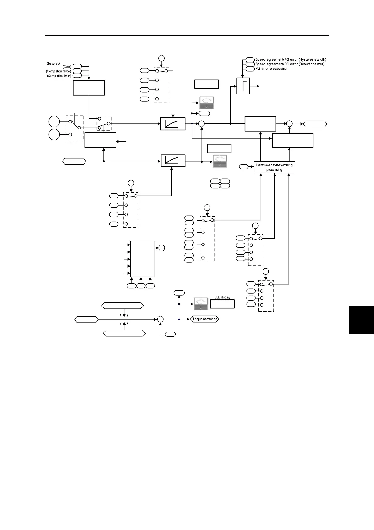
Fig. 8.7-9 Vector control (PMSM drive 1) section block diagram

 Loading...


