11.9 High Power Factor Power Supply Regeneration PWM Converters (RHC Series)
11-29
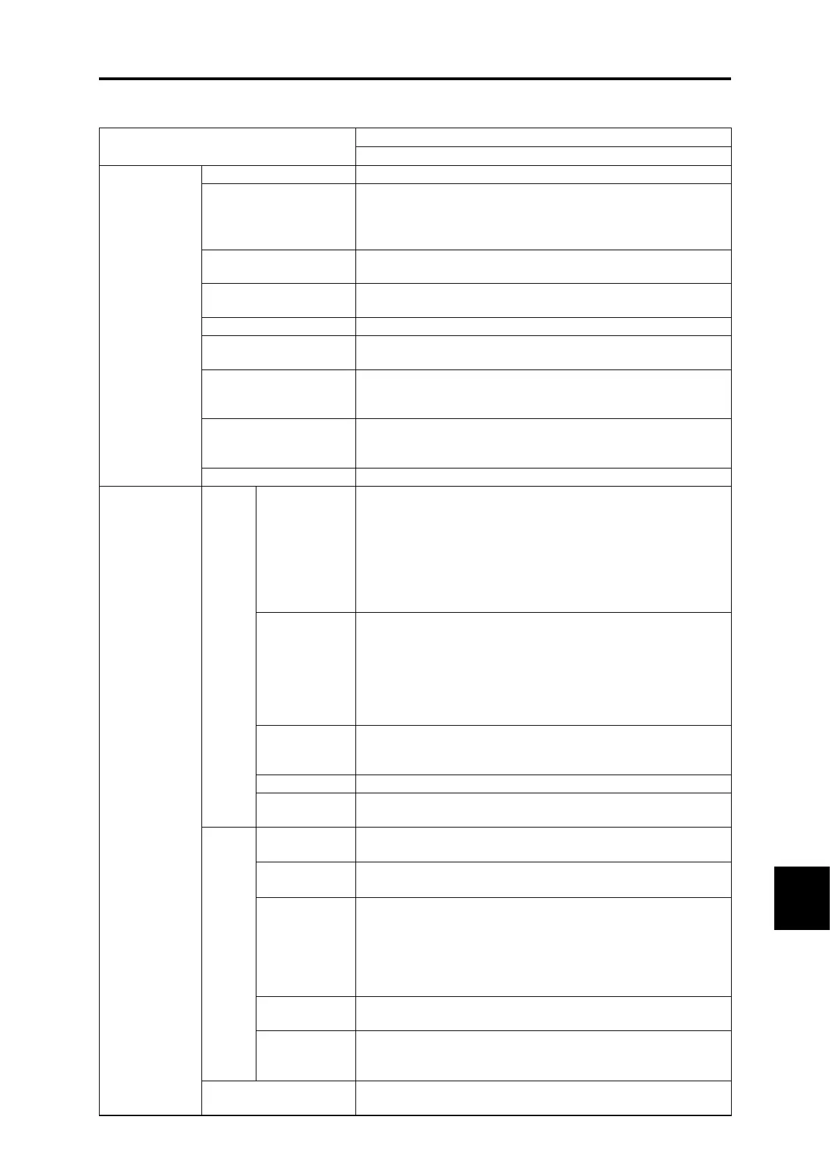
SELECTING PERIPHERAL EQUIPMENT
[ 2 ] Common Specifications
By turning the power ON following connection, rectification is performed,
boosting operation is performed with a run command (short
circuit across RUN-CM, or run command via communication),
and the unit is ready for operation.
Running, powering, regenerating, ready for operation, batch
fault, etc.
MD (CT)/LD (VT)
switching
MD (CT): Overload rating of 150% for 1 min, LD (VT): overload
rating of 120% for 1 min selection
2.5 to 15 Hz (see individual specifications for details.)
0.99 or higher (with 100% load, excl. when equipped with OPC-
RHCE-TBSI-□) (*1)
A conversion coefficient of Ki = 0 can be used in accordance
with the harmonic suppression countermeasure guidelines
issued by the Ministry of Economy, Trade and Industry.
Restart after momentary
power failure
When a momentary power failure occurs, the gate is shut off at
the insufficient voltage level, and the converter resumes
operation automatically following recovery.
Control is possible at the previously set limit value or less.
Alarm display
(protective
functions)
AC fuse blown, AC overvoltage, AC undervoltage, AC overcurrent,
AC input current error, input phase loss, synchronous power
supply frequency error, DC fuse blown (*2), DC overvoltage, DC
undervoltage, charging circuit error, fin overheating, external fault,
converter overheating, overload, memory error, touch panel
communication error, CPU error, network equipment error,
operating procedure mistake, A/D converter error, optical network
error, DC fan lock, hardware error, simulation failure
The latest and older alarm codes (up to 10 times), and the latest
and older alarm detailed information (up to 10 times) are saved
and displayed, and the date and time at which alarms occurred
are saved and displayed with the calendar/clock display function
(accuracy: ±27 sec/month (Ta = 25 °C).
Storage period: 5 years or longer (ambient temperature: 25 °C)
* Battery: Built into models of all capacities as standard)
Displays input power, input RMS current value, input RMS
voltage value, intermediate DC current, and power supply
frequency (alarm code).
The load factor can be measured from the keypad.
Function codes can be set and referenced in Japanese, English,
Chinese, and Korean (4 languages).
Sampling data stored in the converter is read and displayed in a graph.
Sampling time: 62.5 us to 1 s
Data is read from the converter in real time and displayed in a graph.
Sampling time: 1 ms to 1 s
Sampling data stored in the converter is read when an alarm
occurs and displayed in a graph.
Sampling time: 62.5 us to 1 s (However, for other than current, the
traceback function can be used with sampling time of 400 us or longer.)
Sampling data is retained in the memory using battery power.
Retention time: 5 years or longer (ambient temperature: 25 °C)
I/O monitoring, system monitoring, and alarm history monitoring,
etc. can be performed.
The function code setting status can be checked.
Function code settings can be edited, transferred, compared,
and initialized.
Lights up while power is being supplied to the converter unit.
Lights up when there is control power.

 Loading...


