EasyManua.ls Logo

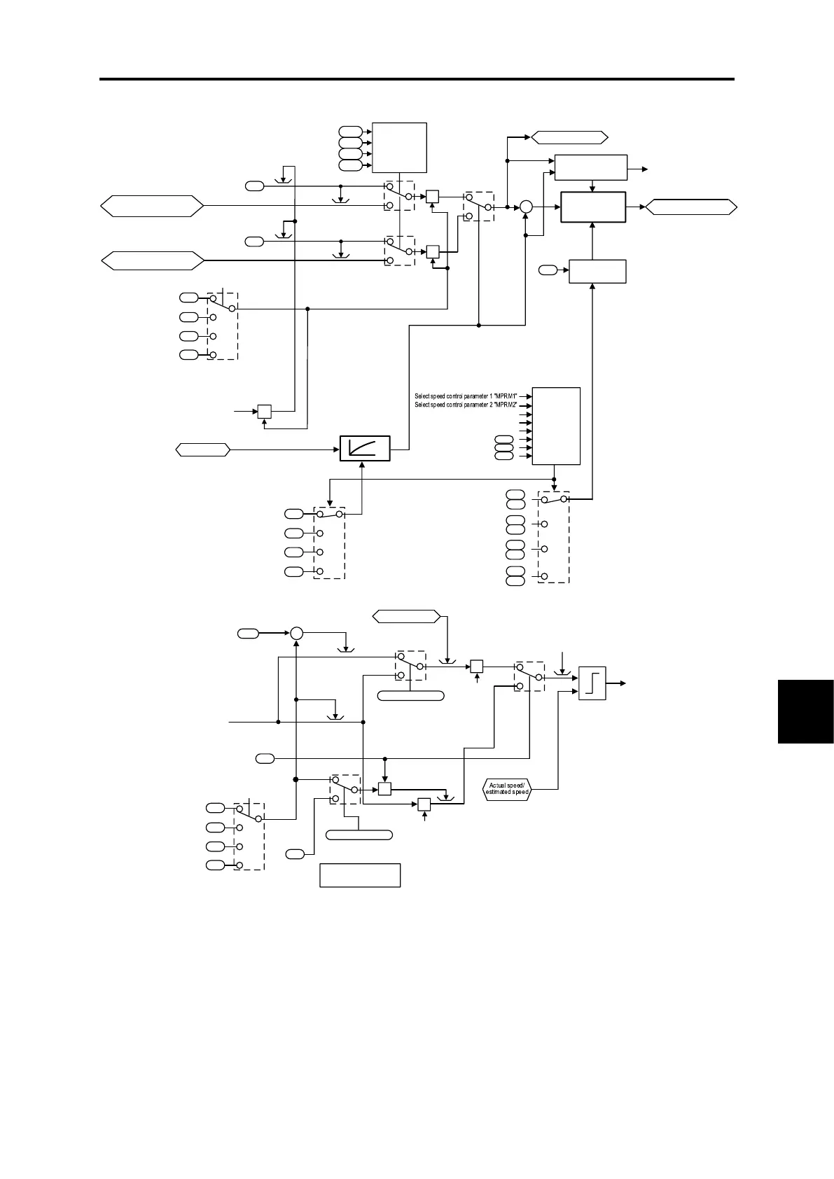
Fuji Electric FRENIC MEGA G2 Series - 4 ] Speed Limit and over Speed Protection Processing

Fuji Electric FRENIC MEGA G2 Series
970 pages
To Next Page IconTo Next Page
To Previous Page IconTo Previous Page
Loading...
8.7 Control Section
8-15
BLOCK DIAGRAMS FOR CONTROL LOGIC
Chap 8
[ 4 ] Speed limit and over speed protection processing
=999
999
120 %
=3,4
=5,6,15,16
F42/A14/b14/r14
+
+
d35
H76
F03
A01
d32
d33
Speed limit
value
selector
E61
E62
E63
Parameter
selector
Parameter
sof t-switching
processing
d03
A45
b45
r46
d04
A46
b46
r45
}
}
}
}
d25
ASR
switching time
d02
A44
b44
r44
Alarm
OS
X
X
X
X
120 %
X
=17
=18
18
17
÷
-
+
Speed limit
start/stop decision
Auto speed
regulator
(ASR)
Speed limit value
b01
r01
E66
A42
b42
r42
F03
A01
b01
r01
F03
F42/A14/b14/r14
=15,16
=5,6
599 Hz
599 Hz
Immediate alarm OS
when 599 Hz or higher
Speed limiting
S-LIM
Analog speed limit value
(FWD)
Analog speed limit value
(REV)
Speed limit
Speed limit
Select motor
"M2" "M3" "M4"
Maximum frequency 1
Maximum frequency 2
Maximum frequency 3
Maximum frequency 4
Max. frequency of the specification
599 Hz
Actual speed
Speed detection filter
Speed control 1 to 4
(Speed detection filter)
Torque Limiter (braking)
(Frequency increment Limit)
Over speed detection level
Max. frequency of the specification
Maximum Frequency 1
Maximum Frequency 2
Maximum Frequency 3
Maximum Frequency 4
Select motor
"M2" "M3" "M4"
Drive Control
Selection
Motor selection 1 only
enabled when using PM
Speed limit value
Drive Control
Selection
Parameter selector 1 to 4
Select motor 2 "M2"
Select motor 3 "M3"
Select motor 4 "M4"
Parameter switching 2
Parameter switching 3
Parameter switching 4
Speed control 1 to 4
P (Gain)
I (Integral time)
Comp ensat ion tor que for
speed limit
Fig. 8.7-7 Vector control (speed control / over speed protection processing) section block diagram

Table of Contents

Related product manuals